TOP Contributors

  1. MIKROE (2784 codes)
  2. Alcides Ramos (403 codes)
  3. Shawon Shahryiar (307 codes)
  4. jm_palomino (132 codes)
  5. Bugz Bensce (97 codes)
  6. S P (73 codes)
  7. dany (71 codes)
  8. MikroBUS.NET Team (35 codes)
  9. NART SCHINACKOW (34 codes)
  10. Armstrong Subero (27 codes)

Most Downloaded

  1. Timer Calculator (140977 times)
  2. FAT32 Library (73518 times)
  3. Network Ethernet Library (58326 times)
  4. USB Device Library (48513 times)
  5. Network WiFi Library (44135 times)
  6. FT800 Library (43692 times)
  7. GSM click (30547 times)
  8. mikroSDK (29297 times)
  9. PID Library (27220 times)
  10. microSD click (26931 times)
Libstock prefers package manager

Package Manager

We strongly encourage users to use Package manager for sharing their code on Libstock website, because it boosts your efficiency and leaves the end user with no room for error. [more info]

< Back
mikroSDK Library

AD-SWIO 2 click

Rating:

5

Author: MIKROE

Last Updated: 2020-04-14

Package Version: 1.0.0.0

mikroSDK Library: 1.0.0.0

Category: ADC

Downloaded: 3562 times

Not followed.

License: MIT license  

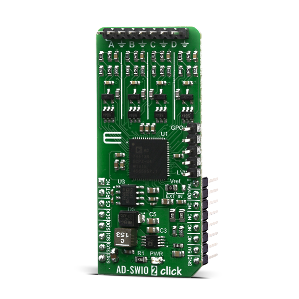
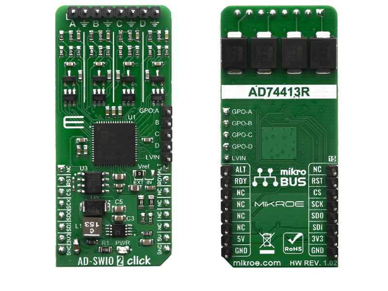
AD-SWIO 2 Click is a Click board equipped with the AD74413R, from Analog Devices. The AD74413R is a quad-channel software configurable input/output solution for building and process control applications. The device provides a fully integrated single chip solution for input and output operation.

No Abuse Reported

Do you want to subscribe in order to receive notifications regarding "AD-SWIO 2 click" changes.

Do you want to unsubscribe in order to stop receiving notifications regarding "AD-SWIO 2 click" changes.

Do you want to report abuse regarding "AD-SWIO 2 click".

  • mikroSDK Library 2.0.0.0
  • Comments (0)
DOWNLOAD LINK RELATED COMPILER CONTAINS
mikroBasic PRO for ARM
  • lib
  • src
  • exa
  • hlp
  • hex
  • sch
  • pcb
  • doc
mikroBasic PRO for AVR
  • lib
  • src
  • exa
  • hlp
  • hex
  • sch
  • pcb
  • doc
mikroBasic PRO for dsPIC30/33 & PIC24
  • lib
  • src
  • exa
  • hlp
  • hex
  • sch
  • pcb
  • doc
mikroBasic PRO for FT90x
  • lib
  • src
  • exa
  • hlp
  • hex
  • sch
  • pcb
  • doc
mikroBasic PRO for PIC
  • lib
  • src
  • exa
  • hlp
  • hex
  • sch
  • pcb
  • doc
mikroBasic PRO for PIC32
  • lib
  • src
  • exa
  • hlp
  • hex
  • sch
  • pcb
  • doc
mikroC PRO for ARM
  • lib
  • src
  • exa
  • hlp
  • hex
  • sch
  • pcb
  • doc
mikroC PRO for AVR
  • lib
  • src
  • exa
  • hlp
  • hex
  • sch
  • pcb
  • doc
mikroC PRO for dsPIC30/33 & PIC24
  • lib
  • src
  • exa
  • hlp
  • hex
  • sch
  • pcb
  • doc
mikroC PRO for FT90x
  • lib
  • src
  • exa
  • hlp
  • hex
  • sch
  • pcb
  • doc
mikroC PRO for PIC
  • lib
  • src
  • exa
  • hlp
  • hex
  • sch
  • pcb
  • doc
mikroC PRO for PIC32
  • lib
  • src
  • exa
  • hlp
  • hex
  • sch
  • pcb
  • doc
mikroPascal PRO for ARM
  • lib
  • src
  • exa
  • hlp
  • hex
  • sch
  • pcb
  • doc
mikroPascal PRO for AVR
  • lib
  • src
  • exa
  • hlp
  • hex
  • sch
  • pcb
  • doc
mikroPascal PRO for dsPIC30/33 & PIC24
  • lib
  • src
  • exa
  • hlp
  • hex
  • sch
  • pcb
  • doc
mikroPascal PRO for FT90x
  • lib
  • src
  • exa
  • hlp
  • hex
  • sch
  • pcb
  • doc
mikroPascal PRO for PIC
  • lib
  • src
  • exa
  • hlp
  • hex
  • sch
  • pcb
  • doc
mikroPascal PRO for PIC32
  • lib
  • src
  • exa
  • hlp
  • hex
  • sch
  • pcb
  • doc

mikroSDK Library Blog

AD-SWIO 2 click

AD-SWIO 2 click

Native view of the AD-SWIO 2 click board.

View full image
AD-SWIO 2 click

AD-SWIO 2 click

Front and back view of the AD-SWIO 2 click board.

View full image

Library Description

This library has ability to perform a full control of the AD-SWIO 2 Click board. This click can convert and measure voltage, current and resistance from 4 independent channels and 4 different diagnostics.

Key functions:

  • adswio2_err_t adswio2_generic_write( uint8_t reg_addr, uint16_t data_in ) - This function writes 16-bit data to the selected register.
  • adswio2_err_t adswio2_set_ch_func( uint8_t channel, uint8_t ch_func ) - This function allows user to modify the functionality of the selected channel.
  • adswio2_err_t adswio2_get_conv_results( uint8_t channel, uint16_t *data_out ) - This function allows user to get the converted results of the selected channel.

Examples description

The application is composed of three sections :

  • System Initialization - Initializes all necessary peripherals and pins used for this click. Also initializes uart console module.
  • Application Initialization - Performs a hardware reset of the click board and executes a default configuration which includes that channel A will be enabled to measure voltage input in the range from 0V to 10V, with 4k8 SPS sample rating. In this function also Silicon Revision ID will be checked.
  • Application Task - (code snippet) - Waits until data from the enabled channel is ready and then reads results of conversion for channel A and if response is ok, prints the results on the uart console.
void application_task( )
{
    adswio2_rdy = adswio2_status_pin_ready( );

    while ( adswio2_rdy == 0 )
    {
        adswio2_rdy = adswio2_status_pin_ready( );
    }
    
    adswio2_err = adswio2_get_conv_results( _ADSWIO2_SETUP_CONV_EN_CHA,
                                            &adswio2_ch_a );

    if ( adswio2_err == _ADSWIO2_ERR_STATUS_OK )
    {
        adswio2_res = adwdio2_ch_a;
        adswio2_res /= _ADSWIO2_RANGE_RESOLUTION;
        adswio2_res *= _ADSWIO2_RANGE_VOLT_MV;
        adswio2_ch_a = adswio2_res;
        
        WordToStr( adswio2_ch_a, adswio2_log );
        Ltrim( adswio2_log );
    
        mikrobus_logWrite( "* CH A converted result is ", _LOG_TEXT );
        mikrobus_logWrite( adswio2_log, _LOG_TEXT );
        mikrobus_logWrite( " mV", _LOG_LINE );
        Delay_ms( 100 );
    }
}

Additional Functions :

  • Application Default Handler - Used to send error report messages from click driver to initialized console module.

Other mikroE Libraries used in the example:

  • Conversions
  • C_String
  • SPI
  • UART

Additional notes and informations

Depending on the development board you are using, you may need USB UART clickUSB UART 2 click or RS232 click to connect to your PC, for development systems with no UART to USB interface available on the board. The terminal available in all MikroElektronika compilers, or any other terminal application of your choice, can be used to read the message.


ALSO FROM THIS AUTHOR

DAC 12 Click

0

DAC 12 Click is a compact add-on board that contains a highly accurate digital-to-analog converter. This board features the DAC60508, a general-purpose octal 12-bit analog voltage-output DAC from Texas Instruments. It includes a 2.5V, 5ppm/°C internal reference, eliminating the need for an external precision reference in most applications, and supports the SPI serial interface, which operates at clock rates up to 40MHz. A user interface-selectable gain configuration provides full-scale output voltages of 1.25V, 2.5V, or 5 V. This Click board™ represents an excellent choice for digital gain and offset adjustment applications, programmable voltage, and current sources, programmable reference, and many more.

[Learn More]

4G LTE 2 Data-NA Click

0

4G LTE 2 Click - Data (for North America) is a compact add-on board providing a secure-cloud multi-band solution offering universal connectivity and reliable performance. This board features the LARA-R6401D, the world’s smallest LTE Cat 1 module from u-blox with coverage for North American region and a built-in MQTT client, representing a data-only solution. Equipped with familiar AT commands set over the UART interface, USB interface, and Network and Status indicators, the LARA-R6401D also has a comprehensive certification scheme, multi-band and multi-mode capabilities providing excellent flexibility, except for the support of voice/audio application.

[Learn More]

STSPIN220 Click

0

STSPIN220 Click is a stepper motor driver with the PWM current control and selectable microstepping up to 256 microsteps. It is based on the STSPIN220, a low voltage stepper motor driver from STSPIN2 series. It is optimized for battery-powered, low voltage motor driving applications, featuring the lowest standby current available on the market (max 80 nA). The STSPIN220 is a high-efficiency motor driver, featuring low ON resistance MOSFETs as the output stage, in a small 3x3mm QFN package. Its output stage implements the PWM current control with fixed OFF time, along with a full set of protection features. The device can be used with the step motor voltage ranging from 1.8V to 10V, and current up to 1.3A per bridge.

[Learn More]