TOP Contributors

  1. MIKROE (2784 codes)
  2. Alcides Ramos (405 codes)
  3. Shawon Shahryiar (307 codes)
  4. jm_palomino (133 codes)
  5. Bugz Bensce (97 codes)
  6. S P (73 codes)
  7. dany (71 codes)
  8. MikroBUS.NET Team (35 codes)
  9. NART SCHINACKOW (34 codes)
  10. Armstrong Subero (27 codes)

Most Downloaded

  1. Timer Calculator (141623 times)
  2. FAT32 Library (74647 times)
  3. Network Ethernet Library (59125 times)
  4. USB Device Library (49163 times)
  5. Network WiFi Library (44925 times)
  6. FT800 Library (44456 times)
  7. GSM click (31119 times)
  8. mikroSDK (30016 times)
  9. microSD click (27531 times)
  10. PID Library (27512 times)
Libstock prefers package manager

Package Manager

We strongly encourage users to use Package manager for sharing their code on Libstock website, because it boosts your efficiency and leaves the end user with no room for error. [more info]

< Back
mikroSDK Library

MIC 3 click

Rating:

5

Author: MIKROE

Last Updated: 2020-06-10

Package Version: 1.0.0.0

mikroSDK Library: 1.0.0.0

Category: Microphone

Downloaded: 3045 times

Not followed.

License: MIT license  

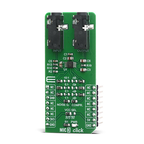
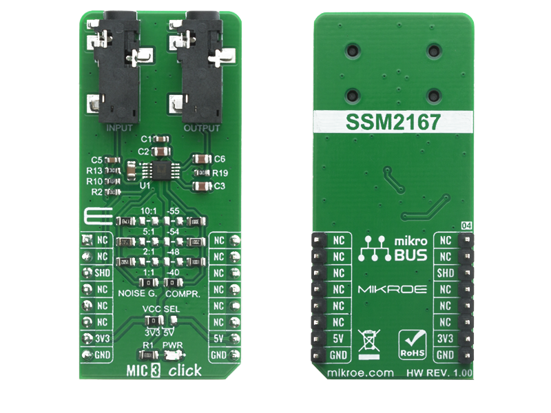
The MIC 3 Click is a Click board that features the SSM2167-1RMZ-R7, a Microphone Preamplifier, from Analog Device.The Click board is a low voltage Microphone preamplifier with Variable compression and noise gating.

No Abuse Reported

Do you want to subscribe in order to receive notifications regarding "MIC 3 click" changes.

Do you want to unsubscribe in order to stop receiving notifications regarding "MIC 3 click" changes.

Do you want to report abuse regarding "MIC 3 click".

  • mikroSDK Library 2.0.0.0
  • Comments (0)
DOWNLOAD LINK RELATED COMPILER CONTAINS
mikroBasic PRO for ARM
  • lib
  • src
  • exa
  • hlp
  • hex
  • sch
  • pcb
  • doc
mikroBasic PRO for AVR
  • lib
  • src
  • exa
  • hlp
  • hex
  • sch
  • pcb
  • doc
mikroBasic PRO for dsPIC30/33 & PIC24
  • lib
  • src
  • exa
  • hlp
  • hex
  • sch
  • pcb
  • doc
mikroBasic PRO for FT90x
  • lib
  • src
  • exa
  • hlp
  • hex
  • sch
  • pcb
  • doc
mikroBasic PRO for PIC
  • lib
  • src
  • exa
  • hlp
  • hex
  • sch
  • pcb
  • doc
mikroBasic PRO for PIC32
  • lib
  • src
  • exa
  • hlp
  • hex
  • sch
  • pcb
  • doc
mikroC PRO for ARM
  • lib
  • src
  • exa
  • hlp
  • hex
  • sch
  • pcb
  • doc
mikroC PRO for AVR
  • lib
  • src
  • exa
  • hlp
  • hex
  • sch
  • pcb
  • doc
mikroC PRO for dsPIC30/33 & PIC24
  • lib
  • src
  • exa
  • hlp
  • hex
  • sch
  • pcb
  • doc
mikroC PRO for FT90x
  • lib
  • src
  • exa
  • hlp
  • hex
  • sch
  • pcb
  • doc
mikroC PRO for PIC
  • lib
  • src
  • exa
  • hlp
  • hex
  • sch
  • pcb
  • doc
mikroC PRO for PIC32
  • lib
  • src
  • exa
  • hlp
  • hex
  • sch
  • pcb
  • doc
mikroPascal PRO for ARM
  • lib
  • src
  • exa
  • hlp
  • hex
  • sch
  • pcb
  • doc
mikroPascal PRO for AVR
  • lib
  • src
  • exa
  • hlp
  • hex
  • sch
  • pcb
  • doc
mikroPascal PRO for dsPIC30/33 & PIC24
  • lib
  • src
  • exa
  • hlp
  • hex
  • sch
  • pcb
  • doc
mikroPascal PRO for FT90x
  • lib
  • src
  • exa
  • hlp
  • hex
  • sch
  • pcb
  • doc
mikroPascal PRO for PIC
  • lib
  • src
  • exa
  • hlp
  • hex
  • sch
  • pcb
  • doc
mikroPascal PRO for PIC32
  • lib
  • src
  • exa
  • hlp
  • hex
  • sch
  • pcb
  • doc

mikroSDK Library Blog

MIC 3 Click

MIC 3 Click

Native view of the MIC 3 Click board.

View full image
MIC 3 Click

MIC 3 Click

Front and back view of the MIC 3 Click board.

View full image

Library Description

Library provides function for setting state of the pin, and function for GPIO mapping.

Key functions:

  • void mic3_set_shd_pin ( uint8_t state ) - Function for setting shd pin state

Examples description

The application is composed of three sections :

  • System Initialization - Initialization of SHD to output and log module
  • Application Initialization - Maps GPIO for Mikrobus1, and sets SHD pin to HIGH state
void application_init ( )
{
    mikrobus_logWrite( " ***** APP INIT ***** ", _LOG_LINE );
    mic3_gpio_driver_init( (mic3_obj_t)&_MIKROBUS1_GPIO );
    mic3_set_shd_pin( MIC3_PIN_STATE_HIGH );
    mikrobus_logWrite( " ***** APP TASK ***** ", _LOG_LINE );
    mikrobus_logWrite( " - Microphone is turned on - ", _LOG_LINE );
}

Other mikroE Libraries used in the example:

  • UART

Additional notes and informations

Depending on the development board you are using, you may need USB UART clickUSB UART 2 click or RS232 click to connect to your PC, for development systems with no UART to USB interface available on the board. The terminal available in all MikroElektronika compilers, or any other terminal application of your choice, can be used to read the message.

ALSO FROM THIS AUTHOR

Mikromedia+ for STM32 ARM - RF Communication Example

5

This is demonstration project how Mikromedia+ for STM communicate over RF. Data is send over simple 'led protocol' (1 byte command). Development board for STM32 with an add-on board nRF Click is used as a receiver device.

[Learn More]

LED Driver 16 Click

0

LED Driver 16 Click is a compact add-on board that simplifies the control of multiple LEDs. This board features the PCA9745B, an SPI-configurable sixteen-channel constant current LED driver from NXP Semiconductors. Each LED output has an 8-bit resolution (256 steps) fixed-frequency individual PWM controller that operates at 31.25kHz with an adjustable duty cycle from 0 to 100% to allow the LED to be set to a specific brightness value. Powered through a selected mikroBUS™ power rail, either 3.3V or 5V, it provides a maximum output current of 57mA per channel and multiple built-in protection functions that protect the circuit during abnormalities.

[Learn More]

Hall Current 13 Click

0

Hall Current 13 Click is a compact add-on board that provides economical and precise AC or DC current sensing solutions. This board features the TMCS1107-Q1, a galvanically isolated Hall-effect current sensor capable of DC or AC current measurement with high accuracy, excellent linearity, and temperature stability from Texas Instruments. It enables the lowest drift, <3% full-scale error, and highest accuracy over time and temperature. It also provides a reliable 420V lifetime working voltage and 3kVRMS isolation between the current path and circuitry with uni/bidirectional current sensing. Besides, the user is allowed to process the output signal in analog or digital form.

[Learn More]