TOP Contributors

  1. MIKROE (2653 codes)
  2. Alcides Ramos (351 codes)
  3. Shawon Shahryiar (307 codes)
  4. jm_palomino (112 codes)
  5. Chisanga Mumba (90 codes)
  6. S P (73 codes)
  7. dany (71 codes)
  8. MikroBUS.NET Team (35 codes)
  9. NART SCHINACKOW (34 codes)
  10. Armstrong Subero (27 codes)

Most Downloaded

  1. Timer Calculator (136652 times)
  2. FAT32 Library (69874 times)
  3. Network Ethernet Library (55904 times)
  4. USB Device Library (46245 times)
  5. Network WiFi Library (41880 times)
  6. FT800 Library (41115 times)
  7. GSM click (28968 times)
  8. PID Library (26404 times)
  9. mikroSDK (26333 times)
  10. microSD click (25345 times)
Libstock prefers package manager

Package Manager

We strongly encourage users to use Package manager for sharing their code on Libstock website, because it boosts your efficiency and leaves the end user with no room for error. [more info]

< Back
mikroSDK Library

RS485 5 click

Rating:

5

Author: MIKROE

Last Updated: 2020-06-18

Package Version: 1.0.0.0

mikroSDK Library: 1.0.0.0

Category: RS485

Downloaded: 2125 times

Not followed.

License: MIT license  

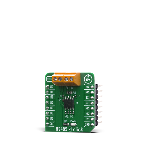
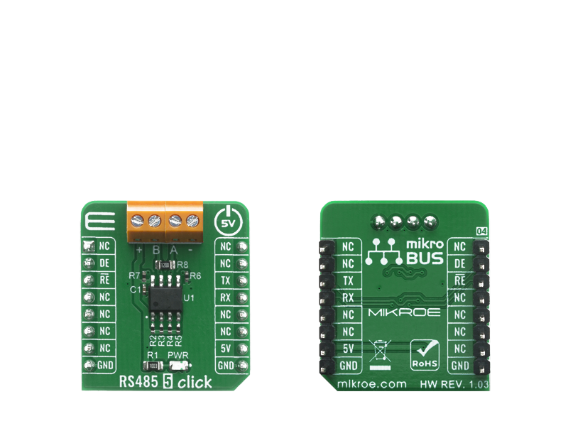
The RS485 5 Click is a Click board equipped with the MAX485, low-power transceiver for RS-485 and RS-422 communication over UART interface for various automation systems, controllers, sensors and small embedded devices that can all share the same bus.

No Abuse Reported

Do you want to subscribe in order to receive notifications regarding "RS485 5 click" changes.

Do you want to unsubscribe in order to stop receiving notifications regarding "RS485 5 click" changes.

Do you want to report abuse regarding "RS485 5 click".

  • mikroSDK Library 2.0.0.0
  • Comments (0)
DOWNLOAD LINK RELATED COMPILER CONTAINS
mikroBasic PRO for ARM
  • lib
  • src
  • exa
  • hlp
  • hex
  • sch
  • pcb
  • doc
mikroBasic PRO for AVR
  • lib
  • src
  • exa
  • hlp
  • hex
  • sch
  • pcb
  • doc
mikroBasic PRO for dsPIC30/33 & PIC24
  • lib
  • src
  • exa
  • hlp
  • hex
  • sch
  • pcb
  • doc
mikroBasic PRO for FT90x
  • lib
  • src
  • exa
  • hlp
  • hex
  • sch
  • pcb
  • doc
mikroBasic PRO for PIC
  • lib
  • src
  • exa
  • hlp
  • hex
  • sch
  • pcb
  • doc
mikroBasic PRO for PIC32
  • lib
  • src
  • exa
  • hlp
  • hex
  • sch
  • pcb
  • doc
mikroC PRO for ARM
  • lib
  • src
  • exa
  • hlp
  • hex
  • sch
  • pcb
  • doc
mikroC PRO for AVR
  • lib
  • src
  • exa
  • hlp
  • hex
  • sch
  • pcb
  • doc
mikroC PRO for dsPIC30/33 & PIC24
  • lib
  • src
  • exa
  • hlp
  • hex
  • sch
  • pcb
  • doc
mikroC PRO for FT90x
  • lib
  • src
  • exa
  • hlp
  • hex
  • sch
  • pcb
  • doc
mikroC PRO for PIC
  • lib
  • src
  • exa
  • hlp
  • hex
  • sch
  • pcb
  • doc
mikroC PRO for PIC32
  • lib
  • src
  • exa
  • hlp
  • hex
  • sch
  • pcb
  • doc
mikroPascal PRO for ARM
  • lib
  • src
  • exa
  • hlp
  • hex
  • sch
  • pcb
  • doc
mikroPascal PRO for AVR
  • lib
  • src
  • exa
  • hlp
  • hex
  • sch
  • pcb
  • doc
mikroPascal PRO for dsPIC30/33 & PIC24
  • lib
  • src
  • exa
  • hlp
  • hex
  • sch
  • pcb
  • doc
mikroPascal PRO for FT90x
  • lib
  • src
  • exa
  • hlp
  • hex
  • sch
  • pcb
  • doc
mikroPascal PRO for PIC
  • lib
  • src
  • exa
  • hlp
  • hex
  • sch
  • pcb
  • doc
mikroPascal PRO for PIC32
  • lib
  • src
  • exa
  • hlp
  • hex
  • sch
  • pcb
  • doc

mikroSDK Library Blog

RS485 5 Click

RS485 5 Click

Native view of the RS485 5 Click board.

View full image
RS485 5 Click

RS485 5 Click

Front and back view of the RS485 5 Click board.

View full image

Library Description

Library provides functions for communication over UART module with the device, controlling RE( Receiver Output Enable ) and DE( Driver Output Enable ) pins state.

Key functions:

  • void rs4855_write_byte ( uint8_t input ) - Function for writing data via UART module.
  • uint8_t rs4855_read_byte( ) - Function for reading data via UART module.
  • void rs4855_set_de_state( uint8_t state ) - Function for setting DE pin state.
  • void rs4855_set_re_state( uint8_t state ) - Function for setting RE pin state.

Examples description

The application is composed of three sections :

  • System Initialization - Intializes UART module
  • Application Initialization - Driver intialization
  • Application Task - Choose one mode (read or write) of task. If you reading it checks if data is ready to be read and then reads one byte and if you are wiriting send data via UART.
void application_task ( )
{
    char tmp;
    uint8_t drdy_flag;

    if ( app_mode == APP_MODE_RECEIVER )
    {
        // RECEIVER - UART polling 

        drdy_flag = rs4855_byte_ready( );

        if ( 1 == drdy_flag )
        {
            tmp = rs4855_read_byte( );
            mikrobus_logWrite( &tmp, _LOG_BYTE );
        }
    }
    else
    {
        // TRANSMITER - TX each 2 sec
      
        for ( tmp = 0; tmp < 9; tmp++ )
        {
            rs4855_write_byte( demo_message_data[ tmp ] );
            mikrobus_logWrite( ">> MESSAGE SENT <<", _LOG_LINE );
        }
        Delay_ms(2000);
    }
}

Other mikroE Libraries used in the example:

  • UART

Additional notes and informations

Depending on the development board you are using, you may need USB UART clickUSB UART 2 click or RS232 click to connect to your PC, for development systems with no UART to USB interface available on the board. The terminal available in all MikroElektronika compilers, or any other terminal application of your choice, can be used to read the message.

ALSO FROM THIS AUTHOR

LED Driver 16 click

0

LED Driver 16 Click is a compact add-on board that simplifies the control of multiple LEDs. This board features the PCA9745B, an SPI-configurable sixteen-channel constant current LED driver from NXP Semiconductors. Each LED output has an 8-bit resolution (256 steps) fixed-frequency individual PWM controller that operates at 31.25kHz with an adjustable duty cycle from 0 to 100% to allow the LED to be set to a specific brightness value. Powered through a selected mikroBUS™ power rail, either 3.3V or 5V, it provides a maximum output current of 57mA per channel and multiple built-in protection functions that protect the circuit during abnormalities.

[Learn More]

ADC 22 click

0

ADC 22 Click is a compact add-on board with a high-performance data converter. This board features the ADS8665, a high-speed single-supply SAR ADC data acquisition system with programmable bipolar input ranges from Texas Instruments. It features a high-speed, high-precision A/D converter based on successive approximation (SAR). This 12-bit resolution ADC with an integrated analog front-end (AFE) input driver circuit can achieve speeds of up to 500ksps.

[Learn More]

Single Cell click

0

The Single Cell click is a Click board™ which features MCP16251 synchronous boost regulator with true load disconnect and MCP1811A low-dropout (LDO) linear regulator that provide an ultra low quiescent current during device operation of about 250nA and can be shut down for 5nA (typical) supply current draw. Given the potential applications of these features, the Single Cell click can be used for one, two and three-cell Alkaline and NiMH/NiCd portable products, solar cell applications, personal care and medical products, smartphones, MP3 players, wireless sensors and many more.

[Learn More]