TOP Contributors

  1. MIKROE (2784 codes)
  2. Alcides Ramos (405 codes)
  3. Shawon Shahryiar (307 codes)
  4. jm_palomino (133 codes)
  5. Bugz Bensce (97 codes)
  6. S P (73 codes)
  7. dany (71 codes)
  8. MikroBUS.NET Team (35 codes)
  9. NART SCHINACKOW (34 codes)
  10. Armstrong Subero (27 codes)

Most Downloaded

  1. Timer Calculator (142085 times)
  2. FAT32 Library (75310 times)
  3. Network Ethernet Library (59504 times)
  4. USB Device Library (49526 times)
  5. Network WiFi Library (45290 times)
  6. FT800 Library (44928 times)
  7. GSM click (31442 times)
  8. mikroSDK (30467 times)
  9. microSD click (27804 times)
  10. PID Library (27625 times)
Libstock prefers package manager

Package Manager

We strongly encourage users to use Package manager for sharing their code on Libstock website, because it boosts your efficiency and leaves the end user with no room for error. [more info]

< Back
mikroSDK Library

Buck & Boost click

Rating:

5

Author: MIKROE

Last Updated: 2020-11-06

Package Version: 1.0.0.0

mikroSDK Library: 1.0.0.0

Category: Buck-Boost

Downloaded: 2864 times

Not followed.

License: MIT license  
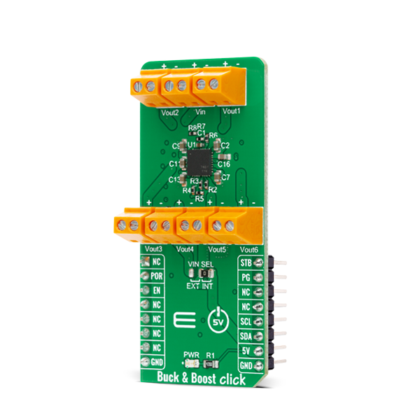
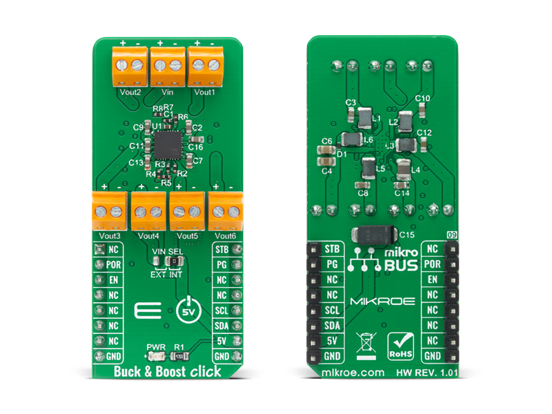
Buck &amp;amp; Boost Click is a compact add-on board that contains a configurable power management device. This board features the MIC7401, a highly-integrated power-management IC featuring five synchronous buck regulators, one boost regulator, and a high-speed I2C interface with an internal EEPROM memory from Microchip.

No Abuse Reported

Do you want to subscribe in order to receive notifications regarding "Buck & Boost click" changes.

Do you want to unsubscribe in order to stop receiving notifications regarding "Buck & Boost click" changes.

Do you want to report abuse regarding "Buck & Boost click".

  • mikroSDK Library 2.0.0.0
  • Comments (0)
DOWNLOAD LINK RELATED COMPILER CONTAINS
mikroBasic PRO for ARM
  • lib
  • src
  • exa
  • hlp
  • hex
  • sch
  • pcb
  • doc
mikroBasic PRO for AVR
  • lib
  • src
  • exa
  • hlp
  • hex
  • sch
  • pcb
  • doc
mikroBasic PRO for dsPIC30/33 & PIC24
  • lib
  • src
  • exa
  • hlp
  • hex
  • sch
  • pcb
  • doc
mikroBasic PRO for FT90x
  • lib
  • src
  • exa
  • hlp
  • hex
  • sch
  • pcb
  • doc
mikroBasic PRO for PIC
  • lib
  • src
  • exa
  • hlp
  • hex
  • sch
  • pcb
  • doc
mikroBasic PRO for PIC32
  • lib
  • src
  • exa
  • hlp
  • hex
  • sch
  • pcb
  • doc
mikroC PRO for ARM
  • lib
  • src
  • exa
  • hlp
  • hex
  • sch
  • pcb
  • doc
mikroC PRO for AVR
  • lib
  • src
  • exa
  • hlp
  • hex
  • sch
  • pcb
  • doc
mikroC PRO for dsPIC30/33 & PIC24
  • lib
  • src
  • exa
  • hlp
  • hex
  • sch
  • pcb
  • doc
mikroC PRO for FT90x
  • lib
  • src
  • exa
  • hlp
  • hex
  • sch
  • pcb
  • doc
mikroC PRO for PIC
  • lib
  • src
  • exa
  • hlp
  • hex
  • sch
  • pcb
  • doc
mikroC PRO for PIC32
  • lib
  • src
  • exa
  • hlp
  • hex
  • sch
  • pcb
  • doc
mikroPascal PRO for ARM
  • lib
  • src
  • exa
  • hlp
  • hex
  • sch
  • pcb
  • doc
mikroPascal PRO for AVR
  • lib
  • src
  • exa
  • hlp
  • hex
  • sch
  • pcb
  • doc
mikroPascal PRO for dsPIC30/33 & PIC24
  • lib
  • src
  • exa
  • hlp
  • hex
  • sch
  • pcb
  • doc
mikroPascal PRO for FT90x
  • lib
  • src
  • exa
  • hlp
  • hex
  • sch
  • pcb
  • doc
mikroPascal PRO for PIC
  • lib
  • src
  • exa
  • hlp
  • hex
  • sch
  • pcb
  • doc
mikroPascal PRO for PIC32
  • lib
  • src
  • exa
  • hlp
  • hex
  • sch
  • pcb
  • doc

mikroSDK Library Blog

Buck &amp; Boost Click

Buck & Boost Click

Native view of the Buck & Boost Click board.

View full image
Buck &amp; Boost Click

Buck & Boost Click

Front and back view of the Buck & Boost Click board.

View full image

Library Description

The library covers all the necessary functions to control Buck & Boost Click board™. Library performs a standard I2C interface communication.

Key functions:

  • void buckandboost_device_enable ( uint8_t state ) - Enable device function.
  • (uint8_t out_value ) - Set buck output voltage function.
  • (buckandboost_status_t *s_data ) - Get status function.

Examples description

The application is composed of three sections :

  • System Initialization - Initializes I2C and start to write log.
  • Application Initialization - Initialization driver enables - I2C, enable and wake up device, set normal mode, set Buck current limit to 1.1 A and save configuration, also write log.
  • Application Task - (code snippet) This is an example which demonstrates the use of Buck & Boost Click board™. The display status is updated every 5 seconds on USART terminal while the application cycles the various voltage values on all channel outputs one by one. Vout[1] - 1.8V, Vout[2] - 1.1V, Vout[3] - 1.8V, Vout[4] - 1.05V, Vout[5] - 1.25V and Vout[6] - 9V. All data logs write on USB uart changes for every 5 sec.
void application_task ( )
{
    check_status = buckandboost_set_buck_out_voltage
    ( BUCKANDBOOST_OUTPUT_CH_1, BUCKANDBOOST_BUCK_OUTPUT_VOLTAGE_1800mV );
    Delay_ms( 10 );

    if ( check_status == BUCKANDBOOST_STATUS_OK )
    {
        mikrobus_logWrite( "  Output Voltage 1 : 1.8V   ", _LOG_LINE );
        mikrobus_logWrite( "- - - - - - - - - - - - - - ", _LOG_LINE );
    }

    buckandboost_send_cmd ( BUCKANDBOOST_CMD_SAVECONFIG );
    buckandboost_get_status ( BUCKANDBOOST_OUTPUT_CH_1, &status_data );
    display_status( );
    Delay_ms( 2000 );

    check_status = buckandboost_set_buck_out_voltage
    ( BUCKANDBOOST_OUTPUT_CH_2, BUCKANDBOOST_BUCK_OUTPUT_VOLTAGE_1100mV );
    Delay_ms( 10 );

    if ( check_status == BUCKANDBOOST_STATUS_OK )
    {
        mikrobus_logWrite( "  Output Voltage 2 : 1.1V   ", _LOG_LINE );
        mikrobus_logWrite( "- - - - - - - - - - - - - - ", _LOG_LINE );
    }

    buckandboost_send_cmd ( BUCKANDBOOST_CMD_SAVECONFIG );
    buckandboost_get_status ( BUCKANDBOOST_OUTPUT_CH_2, &status_data );
    display_status( );

    Delay_ms( 2000 );

    check_status = buckandboost_set_buck_out_voltage
    ( BUCKANDBOOST_OUTPUT_CH_3, BUCKANDBOOST_BUCK_OUTPUT_VOLTAGE_1800mV );
    Delay_ms( 10 );

    if ( check_status == BUCKANDBOOST_STATUS_OK )
    {
        mikrobus_logWrite( "  Output Voltage 3 : 1.8V   ", _LOG_LINE );
        mikrobus_logWrite( "- - - - - - - - - - - - - - ", _LOG_LINE );
    }

    buckandboost_get_status ( BUCKANDBOOST_OUTPUT_CH_3, &status_data );
    display_status( );

    Delay_ms( 2000 );

    check_status = buckandboost_set_buck_out_voltage
    ( BUCKANDBOOST_OUTPUT_CH_4, BUCKANDBOOST_BUCK_OUTPUT_VOLTAGE_1050mV );
    Delay_ms( 10 );

    if ( check_status == BUCKANDBOOST_STATUS_OK )
    {
        mikrobus_logWrite( "  Output Voltage 4 : 1.05V  ", _LOG_LINE );
        mikrobus_logWrite( "- - - - - - - - - - - - - - ", _LOG_LINE );
    }

    buckandboost_get_status ( BUCKANDBOOST_OUTPUT_CH_4, &status_data );
    display_status( );
    Delay_ms( 2000 );

    check_status = buckandboost_set_buck_out_voltage
    ( BUCKANDBOOST_OUTPUT_CH_5, BUCKANDBOOST_BUCK_OUTPUT_VOLTAGE_1250mV );
    Delay_ms( 10 );

    if ( check_status == BUCKANDBOOST_STATUS_OK )
    {
        mikrobus_logWrite( "  Output Voltage 5 : 1.25V  ", _LOG_LINE );
        mikrobus_logWrite( "- - - - - - - - - - - - - - ", _LOG_LINE );
    }
    buckandboost_get_status ( BUCKANDBOOST_OUTPUT_CH_5, &status_data );
    display_status( );
    Delay_ms( 2000 );
    
    check_status = buckandboost_set_boost_out_voltage
    ( BUCKANDBOOST_BOOST_OUTPUT_VOLTAGE_9000mV );
    Delay_ms( 10 );

    if ( check_status == BUCKANDBOOST_STATUS_OK )
    {
        mikrobus_logWrite( "  Output Voltage 6 : 9.00V   ", _LOG_LINE );
        mikrobus_logWrite( "- - - - - - - - - - - - - - ", _LOG_LINE );
    }
    buckandboost_get_status ( BUCKANDBOOST_OUTPUT_CH_6, &status_data );
    display_status( );
    Delay_ms( 2000 );
}

  • void display_status ( void ) - Display status.

Other mikroE Libraries used in the example:

  • I2C
  • UART
  • Conversions

Additional notes and informations

Depending on the development board you are using, you may need USB UART clickUSB UART 2 click or RS232 click to connect to your PC, for development systems with no UART to USB interface available on the board. The terminal available in all MikroElektronika compilers, or any other terminal application of your choice, can be used to read the message.

ALSO FROM THIS AUTHOR

MINI-M4 for Tiva C Series Board Examples

5

Examples for MINI-M4 for Tiva C Series Board. Provided examples demonstrate working with on-board LEDs and internal USB HID module.

[Learn More]

Wheatstone click

5

Wheatstone Click is a measurement Click board which utilizes a Wheatstone bridge circuit onboard, in order to precisely measure the resistance of an external element. Besides the wheatstone bridge circuit, this Click board also utilizes MAX4208 – an ultra-low offset/drift, precision instrumentation amplifier, from Maxim Integrated.

[Learn More]

Ultrasonic 5 Click

0

Ultrasonic 5 Click is a compact add-on board that contains circuits for processing the ultrasonic sensor's output. This board features the TUSS4470, a transformer-drive ultrasonic sensor IC with a logarithmic amplifier from Texas Instruments. In addition to the high selectability of the power supply of the IC itself, this board also allows you to choose between 40kHz and 1MHz operating frequency, with a signal zero crossing comparator as an option. The ultrasonic sensor, the UTR-1440K from PUI Audio, also comes in the same package with this Click board™.

[Learn More]