TOP Contributors

  1. MIKROE (2784 codes)
  2. Alcides Ramos (402 codes)
  3. Shawon Shahryiar (307 codes)
  4. jm_palomino (129 codes)
  5. Bugz Bensce (97 codes)
  6. S P (73 codes)
  7. dany (71 codes)
  8. MikroBUS.NET Team (35 codes)
  9. NART SCHINACKOW (34 codes)
  10. Armstrong Subero (27 codes)

Most Downloaded

  1. Timer Calculator (140786 times)
  2. FAT32 Library (73378 times)
  3. Network Ethernet Library (58203 times)
  4. USB Device Library (48387 times)
  5. Network WiFi Library (43992 times)
  6. FT800 Library (43544 times)
  7. GSM click (30472 times)
  8. mikroSDK (29178 times)
  9. PID Library (27174 times)
  10. microSD click (26850 times)
Libstock prefers package manager

Package Manager

We strongly encourage users to use Package manager for sharing their code on Libstock website, because it boosts your efficiency and leaves the end user with no room for error. [more info]

< Back
mikroSDK Library

I2C MUX 3 click

Rating:

5

Author: MIKROE

Last Updated: 2020-09-16

Package Version: 1.0.0.0

mikroSDK Library: 1.0.0.0

Category: I2C

Downloaded: 2281 times

Not followed.

License: MIT license  

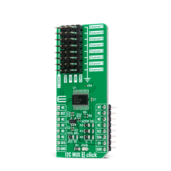
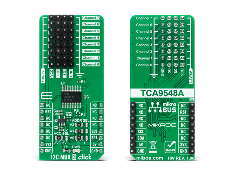
I2C MUX 3 Click is a compact add-on board that contains eight bidirectional translating switches dedicated for applications with I2C slave address conflicts. This board features the TCA9548APWR, a low voltage 8-channel I2C bus switch with an active-low reset input from Texas Instruments.

No Abuse Reported

Do you want to subscribe in order to receive notifications regarding "I2C MUX 3 click" changes.

Do you want to unsubscribe in order to stop receiving notifications regarding "I2C MUX 3 click" changes.

Do you want to report abuse regarding "I2C MUX 3 click".

  • mikroSDK Library 2.0.0.0
  • Comments (0)
DOWNLOAD LINK RELATED COMPILER CONTAINS
mikroBasic PRO for ARM
  • lib
  • src
  • exa
  • hlp
  • hex
  • sch
  • pcb
  • doc
mikroBasic PRO for AVR
  • lib
  • src
  • exa
  • hlp
  • hex
  • sch
  • pcb
  • doc
mikroBasic PRO for dsPIC30/33 & PIC24
  • lib
  • src
  • exa
  • hlp
  • hex
  • sch
  • pcb
  • doc
mikroBasic PRO for FT90x
  • lib
  • src
  • exa
  • hlp
  • hex
  • sch
  • pcb
  • doc
mikroBasic PRO for PIC
  • lib
  • src
  • exa
  • hlp
  • hex
  • sch
  • pcb
  • doc
mikroBasic PRO for PIC32
  • lib
  • src
  • exa
  • hlp
  • hex
  • sch
  • pcb
  • doc
mikroC PRO for ARM
  • lib
  • src
  • exa
  • hlp
  • hex
  • sch
  • pcb
  • doc
mikroC PRO for AVR
  • lib
  • src
  • exa
  • hlp
  • hex
  • sch
  • pcb
  • doc
mikroC PRO for dsPIC30/33 & PIC24
  • lib
  • src
  • exa
  • hlp
  • hex
  • sch
  • pcb
  • doc
mikroC PRO for FT90x
  • lib
  • src
  • exa
  • hlp
  • hex
  • sch
  • pcb
  • doc
mikroC PRO for PIC
  • lib
  • src
  • exa
  • hlp
  • hex
  • sch
  • pcb
  • doc
mikroC PRO for PIC32
  • lib
  • src
  • exa
  • hlp
  • hex
  • sch
  • pcb
  • doc
mikroPascal PRO for ARM
  • lib
  • src
  • exa
  • hlp
  • hex
  • sch
  • pcb
  • doc
mikroPascal PRO for AVR
  • lib
  • src
  • exa
  • hlp
  • hex
  • sch
  • pcb
  • doc
mikroPascal PRO for dsPIC30/33 & PIC24
  • lib
  • src
  • exa
  • hlp
  • hex
  • sch
  • pcb
  • doc
mikroPascal PRO for FT90x
  • lib
  • src
  • exa
  • hlp
  • hex
  • sch
  • pcb
  • doc
mikroPascal PRO for PIC
  • lib
  • src
  • exa
  • hlp
  • hex
  • sch
  • pcb
  • doc
mikroPascal PRO for PIC32
  • lib
  • src
  • exa
  • hlp
  • hex
  • sch
  • pcb
  • doc

mikroSDK Library Blog

I2C MUX 3 Click

I2C MUX 3 Click

Native view of the I2C MUX 3 Click board.

View full image
I2C MUX 3 Click

I2C MUX 3 Click

Front and back view of the I2C MUX 3 Click board.

View full image

Library Description

The library covers all the necessary functions that enables the usage of the I2C MUX 3 click board. User can set one of 8 channels by writing to devices control register and check it by reading, or use the function to set it directly. User can also use sequential read and write function to comunicate with the devices sonnected to the selected channel.

Key functions:

  • uint8_t n_bytes ); - Function is used to write a sequential data starting from the targeted 8-bit register address of the device connected to the desired channel of the I2C MUX 4 click board.
  • uint8_t n_bytes ) - Function is used to read a sequential data starting from the targeted 8-bit register address of the device connected to the desired channel of the I2C MUX 4 click board.
  • void i2cmux3_ch_sel ( uint8_t sel_ch ); - Function is used to select communication channel.

Examples description

The application is composed of three sections :

  • System Initialization - Initializes I2C module, LOG structure and sets RST pin as output.
  • Application Initialization - Initalizes I2C driver, preforms hardware reset and makes an initial log.
  • Application Task - This example shows the capabilities of the I2C MUX 3 click by reading device ID values from eight different click boards and displaying the readings via USART terminal. Some of the used click boards have the same I2C slave addresses, while others do not.
  • Application Note - Click boards used in this example : 6DOF IMU 12 click - https://www.mikroe.com/6dof-imu-12-click RTC 10 click - https://www.mikroe.com/rtc-10-click Surface Temp click - https://www.mikroe.com/surface-temp-click Spectrometer click - https://www.mikroe.com/spectrometer-click Compass 3 click - https://www.mikroe.com/compass-3-click Color 3 click - https://www.mikroe.com/color-3-click 6DOF IMU 11 click - https://www.mikroe.com/6dof-imu-11-click Heart Rate 4 click - https://www.mikroe.com/heart-rate-4-click
void application_task ( )
{
    mikrobus_logWrite( "-------------------------", _LOG_LINE );
    mikrobus_logWrite( "ID values by click board:", _LOG_LINE );
    mikrobus_logWrite( "-------------------------", _LOG_LINE );
    mikrobus_logWrite( "", _LOG_LINE );

    i2cmux3_ch_sel( 0 );
    i2cmux3_rd_slv ( 0x68, 0x00, &id_val, 1 );
    ByteToHex( id_val, log_txt );
    Ltrim( log_txt );
    mikrobus_logWrite( " 6DOF IMU 12  : 0x", _LOG_TEXT );
    mikrobus_logWrite( log_txt, _LOG_LINE );
    mikrobus_logWrite( "-------------------------", _LOG_LINE );
    Delay_ms( 100 );

    i2cmux3_ch_sel( 1 );
    i2cmux3_rd_slv ( 0x68, 0x0F, &id_val, 1 );
    ByteToHex( id_val, log_txt );
    Ltrim( log_txt );
    mikrobus_logWrite( " RTC 10       : 0x", _LOG_TEXT );
    mikrobus_logWrite( log_txt, _LOG_LINE );
    mikrobus_logWrite( "-------------------------", _LOG_LINE );
    Delay_ms( 100 );

    i2cmux3_ch_sel( 2 );
    i2cmux3_rd_slv ( 0x48, 0x0B, &id_val, 1 );
    ByteToHex( id_val, log_txt );
    Ltrim( log_txt );
    mikrobus_logWrite( " Surface Temp : 0x", _LOG_TEXT );
    mikrobus_logWrite( log_txt, _LOG_LINE );
    mikrobus_logWrite( "-------------------------", _LOG_LINE );
    Delay_ms( 100 );
    
    i2cmux3_ch_sel( 3 );
    i2cmux3_rd_slv ( 0x39, 0x92, &id_val, 1 );
    ByteToHex( id_val, log_txt );
    Ltrim( log_txt );
    mikrobus_logWrite( " Spectrometer : 0x", _LOG_TEXT );
    mikrobus_logWrite( log_txt, _LOG_LINE );
    mikrobus_logWrite( "-------------------------", _LOG_LINE );
    Delay_ms( 100 );
    
    i2cmux3_ch_sel( 4 );
    i2cmux3_rd_slv ( 0x30, 0x2F, &id_val, 1 );
    ByteToHex( id_val, log_txt );
    Ltrim( log_txt );
    mikrobus_logWrite( " Compass 3    : 0x", _LOG_TEXT );
    mikrobus_logWrite( log_txt, _LOG_LINE );
    mikrobus_logWrite( "-------------------------", _LOG_LINE );
    Delay_ms( 100 );
    
    i2cmux3_ch_sel( 5 );
    i2cmux3_rd_slv ( 0x29, 0x12, &id_val, 1 );
    ByteToHex( id_val, log_txt );
    Ltrim( log_txt );
    mikrobus_logWrite( " Color 3      : 0x", _LOG_TEXT );
    mikrobus_logWrite( log_txt, _LOG_LINE );
    mikrobus_logWrite( "-------------------------", _LOG_LINE );
    Delay_ms( 100 );
    
    i2cmux3_ch_sel( 6 );
    i2cmux3_rd_slv ( 0x0E, 0x00, &id_val, 1 );
    ByteToHex( id_val, log_txt );
    Ltrim( log_txt );
    mikrobus_logWrite( " 6DOF IMU 11  : 0x", _LOG_TEXT );
    mikrobus_logWrite( log_txt, _LOG_LINE );
    mikrobus_logWrite( "-------------------------", _LOG_LINE );
    Delay_ms( 100 );
    
    i2cmux3_ch_sel( 7 );
    i2cmux3_rd_slv ( 0x57, 0xFF, &id_val, 1 );
    ByteToHex( id_val, log_txt );
    Ltrim( log_txt );
    mikrobus_logWrite( " Heart Rate 4 : 0x", _LOG_TEXT );
    mikrobus_logWrite( log_txt, _LOG_LINE );
    mikrobus_logWrite( "-------------------------", _LOG_LINE );
    Delay_ms( 100 );

    mikrobus_logWrite( "", _LOG_LINE );
    mikrobus_logWrite( "-------------------------", _LOG_LINE );
    Delay_ms( 3000 );
}

Other mikroE Libraries used in the example:

  • I2C
  • UART
  • Conversions

Additional notes and informations

Depending on the development board you are using, you may need USB UART clickUSB UART 2 click or RS232 click to connect to your PC, for development systems with no UART to USB interface available on the board. The terminal available in all MikroElektronika compilers, or any other terminal application of your choice, can be used to read the message.

ALSO FROM THIS AUTHOR

Buzzer Click

0

Buzzer Click is a compact add-on board for generating sound signals in various electronic applications. This board features the CPT-7502-65-SMT-TR, a piezoelectric buzzer transducer from CUI Devices, known for its efficient sound output and compact surface-mount design. The buzzer offers a sound pressure level of 65dB and consumes only 1mA of current, making it ideal for battery-powered devices. The board also features the MIKROE 'Click Snap' function, allowing for flexible installation and autonomous operation.

[Learn More]

RGB Driver click demo example

0

This example is made to demonstrate the operation of the RGB Driver click.

[Learn More]

iButton Click

0

iButton Click - is an iButton™ probe Click board™. The iButton is a Analog Devices technology based on Analog's 1-Wire® communication protocol, and a chip usually packed in a robust stainless steel casing. The button-shaped iButton device has two contacts - the lid and the base. These contacts carry the necessary connections down to a sensitive silicone chip, embedded inside the metal button. When the iButton touches the reader probe on the Click board™, it establishes the communication with the host MCU, via the 1-Wire® interface. The communication is almost instant, so it is enough to press the iButton lightly to the probe contacts.

[Learn More]