TOP Contributors

  1. MIKROE (2784 codes)
  2. Alcides Ramos (405 codes)
  3. Shawon Shahryiar (307 codes)
  4. jm_palomino (133 codes)
  5. Bugz Bensce (97 codes)
  6. S P (73 codes)
  7. dany (71 codes)
  8. MikroBUS.NET Team (35 codes)
  9. NART SCHINACKOW (34 codes)
  10. Armstrong Subero (27 codes)

Most Downloaded

  1. Timer Calculator (141958 times)
  2. FAT32 Library (75148 times)
  3. Network Ethernet Library (59420 times)
  4. USB Device Library (49412 times)
  5. Network WiFi Library (45228 times)
  6. FT800 Library (44814 times)
  7. GSM click (31379 times)
  8. mikroSDK (30365 times)
  9. microSD click (27741 times)
  10. PID Library (27595 times)
Libstock prefers package manager

Package Manager

We strongly encourage users to use Package manager for sharing their code on Libstock website, because it boosts your efficiency and leaves the end user with no room for error. [more info]

< Back
mikroSDK Library

H-Bridge Driver click

Rating:

5

Author: MIKROE

Last Updated: 2021-07-12

Package Version: 1.0.0.0

mikroSDK Library: 1.0.0.0

Category: Motor control

Downloaded: 2677 times

Not followed.

License: MIT license  

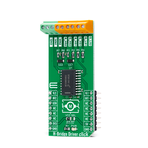
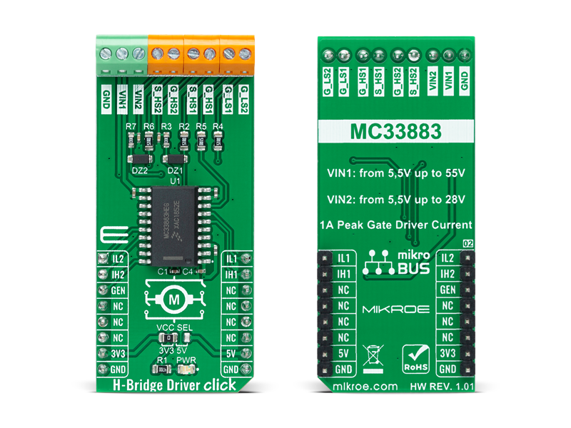
H-Bridge Driver Click is a compact add-on board that contains an H-bridge gate driver, also known as a full-bridge pre-driver. This board features the MC33883, an H-Bridge gate driver with an integrated charge pump and independent high and low side gate drive channels from NXP Semiconductors.

No Abuse Reported

Do you want to subscribe in order to receive notifications regarding "H-Bridge Driver click" changes.

Do you want to unsubscribe in order to stop receiving notifications regarding "H-Bridge Driver click" changes.

Do you want to report abuse regarding "H-Bridge Driver click".

  • mikroSDK Library 2.0.0.0
  • Comments (0)
DOWNLOAD LINK RELATED COMPILER CONTAINS
mikroBasic PRO for ARM
  • lib
  • src
  • exa
  • hlp
  • hex
  • sch
  • pcb
  • doc
mikroBasic PRO for AVR
  • lib
  • src
  • exa
  • hlp
  • hex
  • sch
  • pcb
  • doc
mikroBasic PRO for dsPIC30/33 & PIC24
  • lib
  • src
  • exa
  • hlp
  • hex
  • sch
  • pcb
  • doc
mikroBasic PRO for FT90x
  • lib
  • src
  • exa
  • hlp
  • hex
  • sch
  • pcb
  • doc
mikroBasic PRO for PIC
  • lib
  • src
  • exa
  • hlp
  • hex
  • sch
  • pcb
  • doc
mikroBasic PRO for PIC32
  • lib
  • src
  • exa
  • hlp
  • hex
  • sch
  • pcb
  • doc
mikroC PRO for ARM
  • lib
  • src
  • exa
  • hlp
  • hex
  • sch
  • pcb
  • doc
mikroC PRO for AVR
  • lib
  • src
  • exa
  • hlp
  • hex
  • sch
  • pcb
  • doc
mikroC PRO for dsPIC30/33 & PIC24
  • lib
  • src
  • exa
  • hlp
  • hex
  • sch
  • pcb
  • doc
mikroC PRO for FT90x
  • lib
  • src
  • exa
  • hlp
  • hex
  • sch
  • pcb
  • doc
mikroC PRO for PIC
  • lib
  • src
  • exa
  • hlp
  • hex
  • sch
  • pcb
  • doc
mikroC PRO for PIC32
  • lib
  • src
  • exa
  • hlp
  • hex
  • sch
  • pcb
  • doc
mikroPascal PRO for ARM
  • lib
  • src
  • exa
  • hlp
  • hex
  • sch
  • pcb
  • doc
mikroPascal PRO for AVR
  • lib
  • src
  • exa
  • hlp
  • hex
  • sch
  • pcb
  • doc
mikroPascal PRO for dsPIC30/33 & PIC24
  • lib
  • src
  • exa
  • hlp
  • hex
  • sch
  • pcb
  • doc
mikroPascal PRO for FT90x
  • lib
  • src
  • exa
  • hlp
  • hex
  • sch
  • pcb
  • doc
mikroPascal PRO for PIC
  • lib
  • src
  • exa
  • hlp
  • hex
  • sch
  • pcb
  • doc
mikroPascal PRO for PIC32
  • lib
  • src
  • exa
  • hlp
  • hex
  • sch
  • pcb
  • doc

mikroSDK Library Blog

H-Bridge Driver Click

H-Bridge Driver Click

Native view of the H-Bridge Driver Click board.

View full image
 H-Bridge Driver Click

H-Bridge Driver Click

Front and back view of the H-Bridge Driver Click board.

View full image

Library Description

The library covers all the necessary functions to control the H-Bridge Driver Click board™. User can use functions that control four separate input pins.

Key functions:

  • void hbridgedriver_glo_enable ( uint8_t state ); - Function is used to turn the device on or off.
  • void hbridgedriver_in_ls_2 ( uint8_t state ); - Function is used to set the state of the 'IL2' pin.
  • void hbridgedriver_in_ls_1 ( uint8_t state ); - Function is used to set the state of the 'IL1' pin.

Examples description

The application is composed of three sections :

  • System Initialization - Initializes GPIO and LOG structures, and sets AN, RST, CS, PWM and INT pins as output and start to write log.
  • Application Initialization - Initalizes GPIO driver and turns the device on.
  • Application Task - Demonstrates use of the H-Bridge Driver Click board™ by turning connected MOSFETs gates high or low in order to drive the motor forward, in reverse, brake or coast.
void application_task ( )
{
    mikrobus_logWrite( "The motor turns forward!", _LOG_LINE );
    hbridgedriver_forward( );
    Delay_ms( 1000 );
    mikrobus_logWrite( "The motor brakes!", _LOG_LINE );
    hbridgedriver_braking( );
    Delay_ms( 1000 );
    mikrobus_logWrite( "The motor turns in reverse", _LOG_LINE );
    hbridgedriver_reverse( );
    Delay_ms( 1000 );
    mikrobus_logWrite( "The motor coasting", _LOG_LINE );
    hbridgedriver_coasting( );
    Delay_ms( 1000 );
}

Other mikroE Libraries used in the example:

  • UART

Additional notes and informations

Depending on the development board you are using, you may need USB UART clickUSB UART 2 click or RS232 click to connect to your PC, for development systems with no UART to USB interface available on the board. The terminal available in all MikroElektronika compilers, or any other terminal application of your choice, can be used to read the message.

ALSO FROM THIS AUTHOR

SRAM 2 click

5

SRAM 2 Click is based on ANV32A62A SRAM memory from Anvo-Systems Dresden. It's a 64Kb serial SRAM with a non-volatile SONOS storage element included with each memory cell, organized as 8k words of 8 bits each. The devices are accessed by a two-wire bus. Up to 4 cascadable devices can share the common bus.

[Learn More]

Step Down 3 Click

0

Step Down 3 Click is a compact add-on board that steps down the voltage from its input to its output. This board features the ST1PS03, a nano-quiescent miniaturized synchronous step-down converter with a load switch from STMicroelectronics. The ST1PS03 can provide up to 400mA output current with an input voltage ranging from 1.8V to 5.5V, specifically designed for applications where high efficiency is crucial. It also embeds a controlled switch accessible from auxiliary channel input to supply a subsystem, output voltage from 1.6V to 3.3V set using three digital control inputs, and a Power Good signal to indicate stabilized output voltages.

[Learn More]

Stepper 11 Click

0

Stepper 11 Click is a compact add-on board that contains a bipolar stepper motor driver. This board features the TB9120AFTG, a two-phase bipolar stepping motor driver with a clock input interface and a PWM constant-current control system from Toshiba Semiconductor.

[Learn More]