TOP Contributors

  1. MIKROE (2784 codes)
  2. Alcides Ramos (387 codes)
  3. Shawon Shahryiar (307 codes)
  4. jm_palomino (120 codes)
  5. Bugz Bensce (97 codes)
  6. S P (73 codes)
  7. dany (71 codes)
  8. MikroBUS.NET Team (35 codes)
  9. NART SCHINACKOW (34 codes)
  10. Armstrong Subero (27 codes)

Most Downloaded

  1. Timer Calculator (140167 times)
  2. FAT32 Library (72621 times)
  3. Network Ethernet Library (57641 times)
  4. USB Device Library (47954 times)
  5. Network WiFi Library (43553 times)
  6. FT800 Library (42942 times)
  7. GSM click (30140 times)
  8. mikroSDK (28669 times)
  9. PID Library (27055 times)
  10. microSD click (26552 times)
Libstock prefers package manager

Package Manager

We strongly encourage users to use Package manager for sharing their code on Libstock website, because it boosts your efficiency and leaves the end user with no room for error. [more info]

< Back
mikroSDK Library

Clock Gen 4 click

Rating:

5

Author: MIKROE

Last Updated: 2020-10-22

Package Version: 1.0.0.0

mikroSDK Library: 1.0.0.0

Category: Clock generator

Downloaded: 2118 times

Not followed.

License: MIT license  

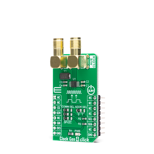
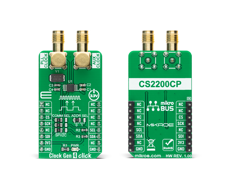
Clock Gen 4 Click is a compact add-on board that contains both a clock generator and a multiplier/jitter reduced clock frequency synthesizer. This board features the CS2200-CP, an analog PLL architecture comprised of a Delta-Sigma fractional-N frequency synthesizer from Cirrus Logic.

No Abuse Reported

Do you want to subscribe in order to receive notifications regarding "Clock Gen 4 click" changes.

Do you want to unsubscribe in order to stop receiving notifications regarding "Clock Gen 4 click" changes.

Do you want to report abuse regarding "Clock Gen 4 click".

  • mikroSDK Library 2.0.0.0
  • Comments (0)
DOWNLOAD LINK RELATED COMPILER CONTAINS
mikroBasic PRO for ARM
  • lib
  • src
  • exa
  • hlp
  • hex
  • sch
  • pcb
  • doc
mikroBasic PRO for AVR
  • lib
  • src
  • exa
  • hlp
  • hex
  • sch
  • pcb
  • doc
mikroBasic PRO for dsPIC30/33 & PIC24
  • lib
  • src
  • exa
  • hlp
  • hex
  • sch
  • pcb
  • doc
mikroBasic PRO for FT90x
  • lib
  • src
  • exa
  • hlp
  • hex
  • sch
  • pcb
  • doc
mikroBasic PRO for PIC
  • lib
  • src
  • exa
  • hlp
  • hex
  • sch
  • pcb
  • doc
mikroBasic PRO for PIC32
  • lib
  • src
  • exa
  • hlp
  • hex
  • sch
  • pcb
  • doc
mikroC PRO for ARM
  • lib
  • src
  • exa
  • hlp
  • hex
  • sch
  • pcb
  • doc
mikroC PRO for AVR
  • lib
  • src
  • exa
  • hlp
  • hex
  • sch
  • pcb
  • doc
mikroC PRO for dsPIC30/33 & PIC24
  • lib
  • src
  • exa
  • hlp
  • hex
  • sch
  • pcb
  • doc
mikroC PRO for FT90x
  • lib
  • src
  • exa
  • hlp
  • hex
  • sch
  • pcb
  • doc
mikroC PRO for PIC
  • lib
  • src
  • exa
  • hlp
  • hex
  • sch
  • pcb
  • doc
mikroC PRO for PIC32
  • lib
  • src
  • exa
  • hlp
  • hex
  • sch
  • pcb
  • doc
mikroPascal PRO for ARM
  • lib
  • src
  • exa
  • hlp
  • hex
  • sch
  • pcb
  • doc
mikroPascal PRO for AVR
  • lib
  • src
  • exa
  • hlp
  • hex
  • sch
  • pcb
  • doc
mikroPascal PRO for dsPIC30/33 & PIC24
  • lib
  • src
  • exa
  • hlp
  • hex
  • sch
  • pcb
  • doc
mikroPascal PRO for FT90x
  • lib
  • src
  • exa
  • hlp
  • hex
  • sch
  • pcb
  • doc
mikroPascal PRO for PIC
  • lib
  • src
  • exa
  • hlp
  • hex
  • sch
  • pcb
  • doc
mikroPascal PRO for PIC32
  • lib
  • src
  • exa
  • hlp
  • hex
  • sch
  • pcb
  • doc

mikroSDK Library Blog

Clock Gen 4 Click

Clock Gen 4 Click

Native view of the Clock Gen 4 Click board.

View full image
Clock Gen 4 Click

Clock Gen 4 Click

Front and back view of the Clock Gen 4 Click board.

View full image

Library Description

The library covers all the necessary functions to control the Clock Gen 4 Click board. User can use functions that allow writting to different registers in order to apply different settings or the ratio between the output signal and the input clock, or to read data using I2C communication exclusively.

Key functions:

  • void clockgen4_dev_ctl ( uint8_t dev_ctl ); - Function is used to write to Device Control register in order to apply settings.
  • void clockgen4_dev_cfg ( uint8_t dev_cfg ); - Function is used to write to Device Configuration 1 register in order to apply settings.
  • uint32_t clockgen4_set_ratio ( float ratio ); - Function is used to set the ratio between the output signal and the input clock.

Examples description

The application is composed of three sections :

  • System Initialization - Initializes I2C and SPI , sets CS pin as output and start to write log.
  • Application Initialization - Initalizes SPI or I2C driver, applies default settings and adjusted ratio to obtain a frequency
  • Application Task - Demonstrates use of Clock Gen 4 click board by changeing output channel every two seconds.
void application_task ( )
{
    clockgen4_dev_ctl ( CLOCKGEN4_AUX_OUT_DIS | CLOCKGEN4_CLK_OUT_EN );
    mikrobus_logWrite( "  PLL Clock          ", _LOG_LINE );
    mikrobus_logWrite( "  output enabled!    ", _LOG_LINE );
    mikrobus_logWrite( "---------------------", _LOG_LINE );
    Delay_ms( 1000 );
    
    clockgen4_dev_ctl ( CLOCKGEN4_AUX_OUT_EN | CLOCKGEN4_CLK_OUT_DIS );
    mikrobus_logWrite( "  AUX Clock          ", _LOG_LINE );
    mikrobus_logWrite( "  output enabled!    ", _LOG_LINE );
    mikrobus_logWrite( "---------------------", _LOG_LINE );
    Delay_ms( 1000 );
}

Other mikroE Libraries used in the example:

  • I2C
  • SPI
  • UART

Additional notes and informations

Depending on the development board you are using, you may need USB UART clickUSB UART 2 click or RS232 click to connect to your PC, for development systems with no UART to USB interface available on the board. The terminal available in all MikroElektronika compilers, or any other terminal application of your choice, can be used to read the message.

ALSO FROM THIS AUTHOR

I2C Isolator 6 Click

0

I2C Isolator 6 Click is a compact add-on board that offers completely isolated bidirectional communication. This board features the ADUM2250, a two-channel, 5kVRMS I2C digital isolator from Analog Devices. The ADUM2250 provides two bidirectional channels, supporting a completely isolated I2C interface that eliminates the need for splitting I2C signals into separate transmit and receive signals for use with standalone optocouplers. It supports data rates from DC up to 1MHz and has a hot swap circuitry to prevent data glitches.

[Learn More]

Fingerprint 4 Click

0

Fingerprint 4 Click is an adapter Click board™ used to interface a compatible fingerprint sensor with the host MCU. This board features FINGERPRINTS BM-Lite Module, a complete biometric fingerprint solution ready to be used out-of-the-box. The BM-Lite Module combines superior biometric performance and a high standard of quality components to offer a comprehensive embedded solution for increased security and enhanced user convenience. It uses a 3D pixel sensing technology that can read virtually any finger, dry or wet, alongside simple serial commands with a configurable communication interface to enroll and verify. Its protective coating helps in protection against ESD, scratches, impact, and everyday wear and tear.

[Learn More]

Current Limit click

5

Current Limit Click is a compact add-on board that contains a low-voltage, P-channel MOSFET power switch intended for high-side load switching applications. This board features the MAX890L, a low-resistance power switch with the adjustable, accurate current limit system, and thermal shutdown from Maxim Integrated.

[Learn More]