TOP Contributors

  1. MIKROE (2784 codes)
  2. Alcides Ramos (387 codes)
  3. Shawon Shahryiar (307 codes)
  4. jm_palomino (120 codes)
  5. Bugz Bensce (97 codes)
  6. S P (73 codes)
  7. dany (71 codes)
  8. MikroBUS.NET Team (35 codes)
  9. NART SCHINACKOW (34 codes)
  10. Armstrong Subero (27 codes)

Most Downloaded

  1. Timer Calculator (140168 times)
  2. FAT32 Library (72621 times)
  3. Network Ethernet Library (57641 times)
  4. USB Device Library (47954 times)
  5. Network WiFi Library (43553 times)
  6. FT800 Library (42942 times)
  7. GSM click (30140 times)
  8. mikroSDK (28669 times)
  9. PID Library (27056 times)
  10. microSD click (26552 times)
Libstock prefers package manager

Package Manager

We strongly encourage users to use Package manager for sharing their code on Libstock website, because it boosts your efficiency and leaves the end user with no room for error. [more info]

< Back
mikroSDK Library

ADC12 click

Rating:

10

Author: MIKROE

Last Updated: 2020-11-12

Package Version: 1.0.0.0

mikroSDK Library: 1.0.0.0

Category: ADC

Downloaded: 2424 times

Not followed.

License: MIT license  

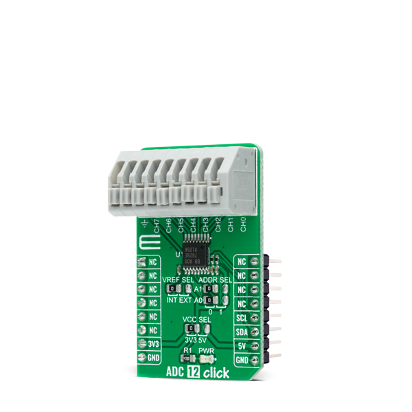
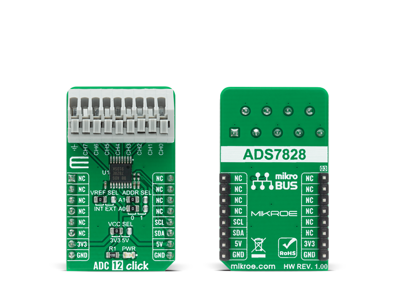
ADC 12 Click is a compact add-on board that contains a fully-featured, general-purpose analog-to-digital converter. This board features the ADS7828, a low-power 12-bit data acquisition device that features a serial I2C interface and an 8-channel multiplexer from Texas Instruments.

No Abuse Reported

Do you want to subscribe in order to receive notifications regarding "ADC12 click" changes.

Do you want to unsubscribe in order to stop receiving notifications regarding "ADC12 click" changes.

Do you want to report abuse regarding "ADC12 click".

  • mikroSDK Library 2.0.0.0
  • Comments (0)
DOWNLOAD LINK RELATED COMPILER CONTAINS
mikroBasic PRO for ARM
  • lib
  • src
  • exa
  • hlp
  • hex
  • sch
  • pcb
  • doc
mikroBasic PRO for AVR
  • lib
  • src
  • exa
  • hlp
  • hex
  • sch
  • pcb
  • doc
mikroBasic PRO for dsPIC30/33 & PIC24
  • lib
  • src
  • exa
  • hlp
  • hex
  • sch
  • pcb
  • doc
mikroBasic PRO for FT90x
  • lib
  • src
  • exa
  • hlp
  • hex
  • sch
  • pcb
  • doc
mikroBasic PRO for PIC
  • lib
  • src
  • exa
  • hlp
  • hex
  • sch
  • pcb
  • doc
mikroBasic PRO for PIC32
  • lib
  • src
  • exa
  • hlp
  • hex
  • sch
  • pcb
  • doc
mikroC PRO for ARM
  • lib
  • src
  • exa
  • hlp
  • hex
  • sch
  • pcb
  • doc
mikroC PRO for AVR
  • lib
  • src
  • exa
  • hlp
  • hex
  • sch
  • pcb
  • doc
mikroC PRO for dsPIC30/33 & PIC24
  • lib
  • src
  • exa
  • hlp
  • hex
  • sch
  • pcb
  • doc
mikroC PRO for FT90x
  • lib
  • src
  • exa
  • hlp
  • hex
  • sch
  • pcb
  • doc
mikroC PRO for PIC
  • lib
  • src
  • exa
  • hlp
  • hex
  • sch
  • pcb
  • doc
mikroC PRO for PIC32
  • lib
  • src
  • exa
  • hlp
  • hex
  • sch
  • pcb
  • doc
mikroPascal PRO for ARM
  • lib
  • src
  • exa
  • hlp
  • hex
  • sch
  • pcb
  • doc
mikroPascal PRO for AVR
  • lib
  • src
  • exa
  • hlp
  • hex
  • sch
  • pcb
  • doc
mikroPascal PRO for dsPIC30/33 & PIC24
  • lib
  • src
  • exa
  • hlp
  • hex
  • sch
  • pcb
  • doc
mikroPascal PRO for FT90x
  • lib
  • src
  • exa
  • hlp
  • hex
  • sch
  • pcb
  • doc
mikroPascal PRO for PIC
  • lib
  • src
  • exa
  • hlp
  • hex
  • sch
  • pcb
  • doc
mikroPascal PRO for PIC32
  • lib
  • src
  • exa
  • hlp
  • hex
  • sch
  • pcb
  • doc

mikroSDK Library Blog

ADC 12 Click

ADC 12 Click

Native view of the ADC 12 Click board.

View full image
ADC 12 Click

ADC 12 Click

Front and back view of the ADC 12 Click board.

View full image

Library Description

The library covers all the necessary functions to control ADC 12 Click board™. User can set or read input mode or power-down mode, read raw adc or voltage and send command to input register or read output.

Key functions:

  • void adc12_send_cmd ( uint8_t cmd_byte ); - Function is used to configure the device.
  • uint16_t adc12_single_ended ( uint8_t chan, uint16_t v_ref ); - Function is used to get raw ADC value.
  • uint16_t adc12_differential ( uint8_t chan, uint16_t v_ref ); - Function is used to get raw ADC value.

Examples description

The application is composed of three sections :

  • System Initialization - Initializes I2C and LOG structures, and start to write log.
  • Application Initialization - Initalizes I2C driver and configures ADC 12 Click board™, enables single-ended inputs, and turns on Internal Reference and ADC.
  • Application Task - This is an example that shows the capabilities of the ADC 12 Click by reading raw value and voltage inputed on channel 0 and displaying data every second.
void application_task ( )
{
    mikrobus_logWrite( "Read Channel 0 raw", _LOG_LINE );
    adc_r = adc12_single_ended ( ADC12_SNGL_END_CH0, ADC12_INT_V_REF_VAL );
    WordToStr( adc_r, log_txt );
    Ltrim( log_txt );
    mikrobus_logWrite( "ADC raw: ", _LOG_TEXT );
    mikrobus_logWrite( log_txt, _LOG_LINE );
    mikrobus_logWrite( "", _LOG_LINE );
    mikrobus_logWrite( "Read Channel 0 voltage", _LOG_LINE );
    adc_v = adc12_single_ended_volt ( ADC12_SNGL_END_CH0, ADC12_INT_V_REF_VAL );
    FloatToStr( adc_v, log_txt );
    Ltrim( log_txt );
    mikrobus_logWrite( "ADC raw: ", _LOG_TEXT );
    mikrobus_logWrite( log_txt, _LOG_TEXT );
    mikrobus_logWrite( "mV", _LOG_LINE );
    mikrobus_logWrite( "------------------------", _LOG_LINE );
    Delay_ms( 1000 );
}

Other mikroE Libraries used in the example:

  • I2C
  • UART
  • Conversions

Additional notes and informations

Depending on the development board you are using, you may need USB UART clickUSB UART 2 click or RS232 click to connect to your PC, for development systems with no UART to USB interface available on the board. The terminal available in all MikroElektronika compilers, or any other terminal application of your choice, can be used to read the message.

ALSO FROM THIS AUTHOR

Opto Encoder 5 Click

0

Opto Encoder 5 Click is a compact add-on board that offers non-contact switching with unparalleled accuracy and precision. This board features the OPB666N, a Photologic® slotted optical switch from TT Electronics, ensuring top-notch performance and reliability. It integrates an 890nm infrared LED and a monolithic integrated circuit with a photodiode, linear amplifier, and Schmitt trigger, all powered effectively by a 5V supply from the mikroBUS™ power rail. The board features an NPN open-collector output configuration and is TTI/LST TL compatible, highlighting its ease of use and versatility.

[Learn More]

Touchpad 3 Click

0

Touchpad 3 Click is a compact add-on board that allows users to easily integrate projected capacitive touch into their applications. This board features the MTCH6301, a turnkey capacitive touch controller that makes it easy for users to use popular multitouch and gesture interfaces from Microchip. This controller’s sophisticated combination of Self and Mutual capacitive scanning for XY touchscreens and touchpads enables several features, including single and dual-touch drawing, the reporting of 11 single-finger gestures, and the detection of up to 10 touches. This Click board™ is suitable for human-machine interfaces, keypad or scrolling functions, single-finger gesture-based interfaces, and more.

[Learn More]

RS485 5V click

0

RS485 click 5V is an RS422/485 transceiver Click board, which can be used as an interface between the TTL level UART and the RS422/485 communication bus.

[Learn More]