TOP Contributors

  1. MIKROE (2784 codes)
  2. Alcides Ramos (405 codes)
  3. Shawon Shahryiar (307 codes)
  4. jm_palomino (133 codes)
  5. Bugz Bensce (97 codes)
  6. S P (73 codes)
  7. dany (71 codes)
  8. MikroBUS.NET Team (35 codes)
  9. NART SCHINACKOW (34 codes)
  10. Armstrong Subero (27 codes)

Most Downloaded

  1. Timer Calculator (141697 times)
  2. FAT32 Library (74777 times)
  3. Network Ethernet Library (59218 times)
  4. USB Device Library (49226 times)
  5. Network WiFi Library (44999 times)
  6. FT800 Library (44536 times)
  7. GSM click (31200 times)
  8. mikroSDK (30103 times)
  9. microSD click (27586 times)
  10. PID Library (27540 times)
Libstock prefers package manager

Package Manager

We strongly encourage users to use Package manager for sharing their code on Libstock website, because it boosts your efficiency and leaves the end user with no room for error. [more info]

< Back
mikroSDK Library

DIGI POT 7 click

Rating:

5

Author: MIKROE

Last Updated: 2021-01-19

Package Version: 1.0.0.0

mikroSDK Library: 1.0.0.0

Category: Digital potentiometer

Downloaded: 2746 times

Not followed.

License: MIT license  

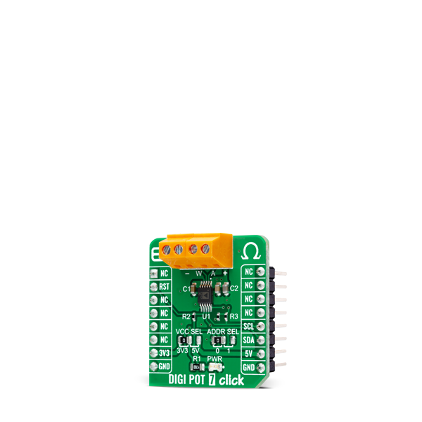
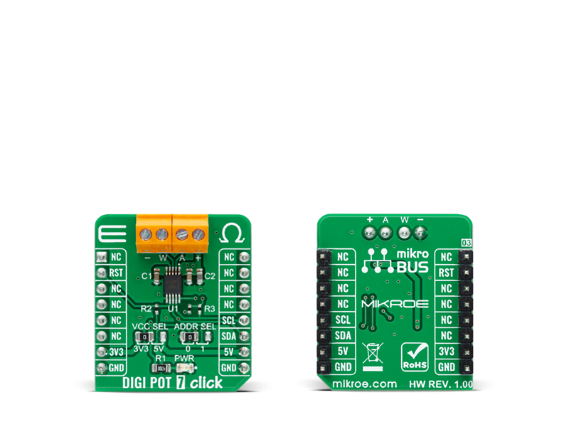
DIGI POT 7 Click is a compact add-on board used as a digitally controlled potentiometer. This board features the AD5175, a single-channel 1024-position digital rheostat with less than ±1% end-to-end resistor tolerance error and 50-time programmable wiper memory from Analog Devices.

No Abuse Reported

Do you want to subscribe in order to receive notifications regarding "DIGI POT 7 click" changes.

Do you want to unsubscribe in order to stop receiving notifications regarding "DIGI POT 7 click" changes.

Do you want to report abuse regarding "DIGI POT 7 click".

  • mikroSDK Library 2.0.0.0
  • Comments (0)
DOWNLOAD LINK RELATED COMPILER CONTAINS
mikroBasic PRO for ARM
  • lib
  • src
  • exa
  • hlp
  • hex
  • sch
  • pcb
  • doc
mikroBasic PRO for AVR
  • lib
  • src
  • exa
  • hlp
  • hex
  • sch
  • pcb
  • doc
mikroBasic PRO for dsPIC30/33 & PIC24
  • lib
  • src
  • exa
  • hlp
  • hex
  • sch
  • pcb
  • doc
mikroBasic PRO for FT90x
  • lib
  • src
  • exa
  • hlp
  • hex
  • sch
  • pcb
  • doc
mikroBasic PRO for PIC
  • lib
  • src
  • exa
  • hlp
  • hex
  • sch
  • pcb
  • doc
mikroBasic PRO for PIC32
  • lib
  • src
  • exa
  • hlp
  • hex
  • sch
  • pcb
  • doc
mikroC PRO for ARM
  • lib
  • src
  • exa
  • hlp
  • hex
  • sch
  • pcb
  • doc
mikroC PRO for AVR
  • lib
  • src
  • exa
  • hlp
  • hex
  • sch
  • pcb
  • doc
mikroC PRO for dsPIC30/33 & PIC24
  • lib
  • src
  • exa
  • hlp
  • hex
  • sch
  • pcb
  • doc
mikroC PRO for FT90x
  • lib
  • src
  • exa
  • hlp
  • hex
  • sch
  • pcb
  • doc
mikroC PRO for PIC
  • lib
  • src
  • exa
  • hlp
  • hex
  • sch
  • pcb
  • doc
mikroC PRO for PIC32
  • lib
  • src
  • exa
  • hlp
  • hex
  • sch
  • pcb
  • doc
mikroPascal PRO for ARM
  • lib
  • src
  • exa
  • hlp
  • hex
  • sch
  • pcb
  • doc
mikroPascal PRO for AVR
  • lib
  • src
  • exa
  • hlp
  • hex
  • sch
  • pcb
  • doc
mikroPascal PRO for dsPIC30/33 & PIC24
  • lib
  • src
  • exa
  • hlp
  • hex
  • sch
  • pcb
  • doc
mikroPascal PRO for FT90x
  • lib
  • src
  • exa
  • hlp
  • hex
  • sch
  • pcb
  • doc
mikroPascal PRO for PIC
  • lib
  • src
  • exa
  • hlp
  • hex
  • sch
  • pcb
  • doc
mikroPascal PRO for PIC32
  • lib
  • src
  • exa
  • hlp
  • hex
  • sch
  • pcb
  • doc

mikroSDK Library Blog

DIGI POT 7 Click

DIGI POT 7 Click

Native view of the DIGI POT 7 Click board.

View full image
DIGI POT 7 Click

DIGI POT 7 Click

Front and back view of the DIGI POT 7 Click board.

View full image

Library Description

The library covers all the necessary functions to control DIGI POT 7 Click board™. Library performs a standard I2C interface communication.

Key functions:

  • void digipot7_enable_write ( void ) - Enable write function.
  • void digipot7_operating_mode ( uint8_t mode ) - Set operating mode function.
  • DIGIPOT7_RETVAL_T digipot7_set_resistance ( uint16_t res_ohm ) - Set resistance function.

Examples description

The application is composed of three sections :

  • System Initialization - Initializes I2C, set RST pin as an output and start to write a log.
  • Application Initialization - Initialization driver enables - I2C, perform a hardware reset, enable write and set to normal operating mode, also write log.
  • Application Task - (code snippet) This is an example that demonstrate the use of the DIGI POT 7 Click board™. In this example we set different resistance values: 1.024 kOhm, 2.048 kOhm, 4.096 kOhm and 8.192 kOhm. Results are being sent to the Usart Terminal where you can track their changes. All data logs write on USB uart changes approximately for every 5 sec.
void application_task ( )
{
    mikrobus_logWrite( " Set Resistance: 1.024 kOhm ", _LOG_LINE );
    mikrobus_logWrite( "----------------------------", _LOG_LINE );
    digipot7_set_resistance( 1024 );
    Delay_ms( 5000 );
    
    mikrobus_logWrite( " Set Resistance: 2.048 kOhm ", _LOG_LINE );
    mikrobus_logWrite( "----------------------------", _LOG_LINE );
    digipot7_set_resistance( 2048 );
    Delay_ms( 5000 );
    
    mikrobus_logWrite( " Set Resistance: 4.096 kOhm ", _LOG_LINE );
    mikrobus_logWrite( "----------------------------", _LOG_LINE );
    digipot7_set_resistance( 4096 );
    Delay_ms( 5000 );
    
    mikrobus_logWrite( " Set Resistance: 8.192 kOhm ", _LOG_LINE );
    mikrobus_logWrite( "----------------------------", _LOG_LINE );
    digipot7_set_resistance( 8192 );
    Delay_ms( 5000 );
}

Other Mikroe Libraries used in the example:

  • I2C
  • UART
  • Conversions

Additional notes and informations

Depending on the development board you are using, you may need USB UART clickUSB UART 2 click or RS232 click to connect to your PC, for development systems with no UART to USB interface available on the board. The terminal available in all MikroElektronika compilers, or any other terminal application of your choice, can be used to read the message.

ALSO FROM THIS AUTHOR

RS232 3 Click

0

RS232 3 Click is a compact add-on board representing a universal usable RS232 transceiver. This board features the SP3221E, a low-power RS232 transceiver from MaxLinear. The SP3221E uses an internal high-efficiency, charge-pump power supply and is compliant with EIA/TIA-232-F standards when powered by any of the mikroBUS™ power rails. The AUTO ON-LINE® feature allows the SP3221E to automatically Wake-Up from a Shutdown state when an RS232 cable is connected and a peripheral device is turned on. When not connected or not in use, the SP3221E will automatically shut down, drawing less supply current.

[Learn More]

RTC 2 click

0

Example for RTC2 click board in mikroBUS form factor. It is a simple demonstration how to read/write date and time from DS1307 RTC (real-time clock). Date and time are read from the RTC every 10 milliseconds and printed on LCD. Communication with the board is done via I2C interface.

[Learn More]

GNSS 17 Click

0

GNSS 17 Click is a compact add-on board for precise and reliable global navigation and positioning. This board features the M20071, an integrated full-function GNSS receiver module from Antenova, which features the MediaTek AG3335MN flash chip. This module can concurrently track multiple GNSS constellations, including GPS, GLONASS, GALILEO, BEIDOU, and QZSS, ensuring accurate positioning even in dense urban environments. It includes advanced features like multi-path algorithms for enhanced accuracy, a high-performance onboard LNA for weak-signal environments, and power-saving modes to optimize energy consumption.

[Learn More]