TOP Contributors

  1. MIKROE (2642 codes)
  2. Alcides Ramos (347 codes)
  3. Shawon Shahryiar (307 codes)
  4. jm_palomino (112 codes)
  5. Chisanga Mumba (90 codes)
  6. S P (73 codes)
  7. dany (71 codes)
  8. MikroBUS.NET Team (35 codes)
  9. NART SCHINACKOW (34 codes)
  10. Armstrong Subero (27 codes)

Most Downloaded

  1. Timer Calculator (136220 times)
  2. FAT32 Library (69487 times)
  3. Network Ethernet Library (55706 times)
  4. USB Device Library (45992 times)
  5. Network WiFi Library (41639 times)
  6. FT800 Library (40782 times)
  7. GSM click (28788 times)
  8. PID Library (26331 times)
  9. mikroSDK (26053 times)
  10. microSD click (25140 times)
Libstock prefers package manager

Package Manager

We strongly encourage users to use Package manager for sharing their code on Libstock website, because it boosts your efficiency and leaves the end user with no room for error. [more info]

< Back
Visual TFT/GLCD Project

ADC + RTC for Mikromedia for ATmega

Rating:

0

Author: Roman Toropov

Last Updated: 2013-05-02

Package Version: 1.0.0.0

Category: Measurement

Downloaded: 918 times

Not followed.

License: MIT license  

Mikromedia for ATmega
Simple example which demonstrates working with the 4-Channel 12-bit A/D Converter (MCP3204) with SPI Serial Interface. The example shows how to measure analog inputs on Channels 0, 1, 2 and 3 and display the results on TFT.
http://youtu.be/cwE1G5faBXc

No Abuse Reported

Do you want to subscribe in order to receive notifications regarding "ADC + RTC for Mikromedia for ATmega" changes.

Do you want to unsubscribe in order to stop receiving notifications regarding "ADC + RTC for Mikromedia for ATmega" changes.

Do you want to report abuse regarding "ADC + RTC for Mikromedia for ATmega".

  • Information
  • Comments (0)
DOWNLOAD LINK RELATED COMPILER CONTAINS
mikroC PRO for AVR
  • lib
  • src
  • exa
  • hlp
  • hex
  • sch
  • pcb
  • doc

Visual TFT/GLCD Project Blog

Video

Example

Watch on YouTube
pcb

pcb

duo clicks, on single-sided PCB

View full image

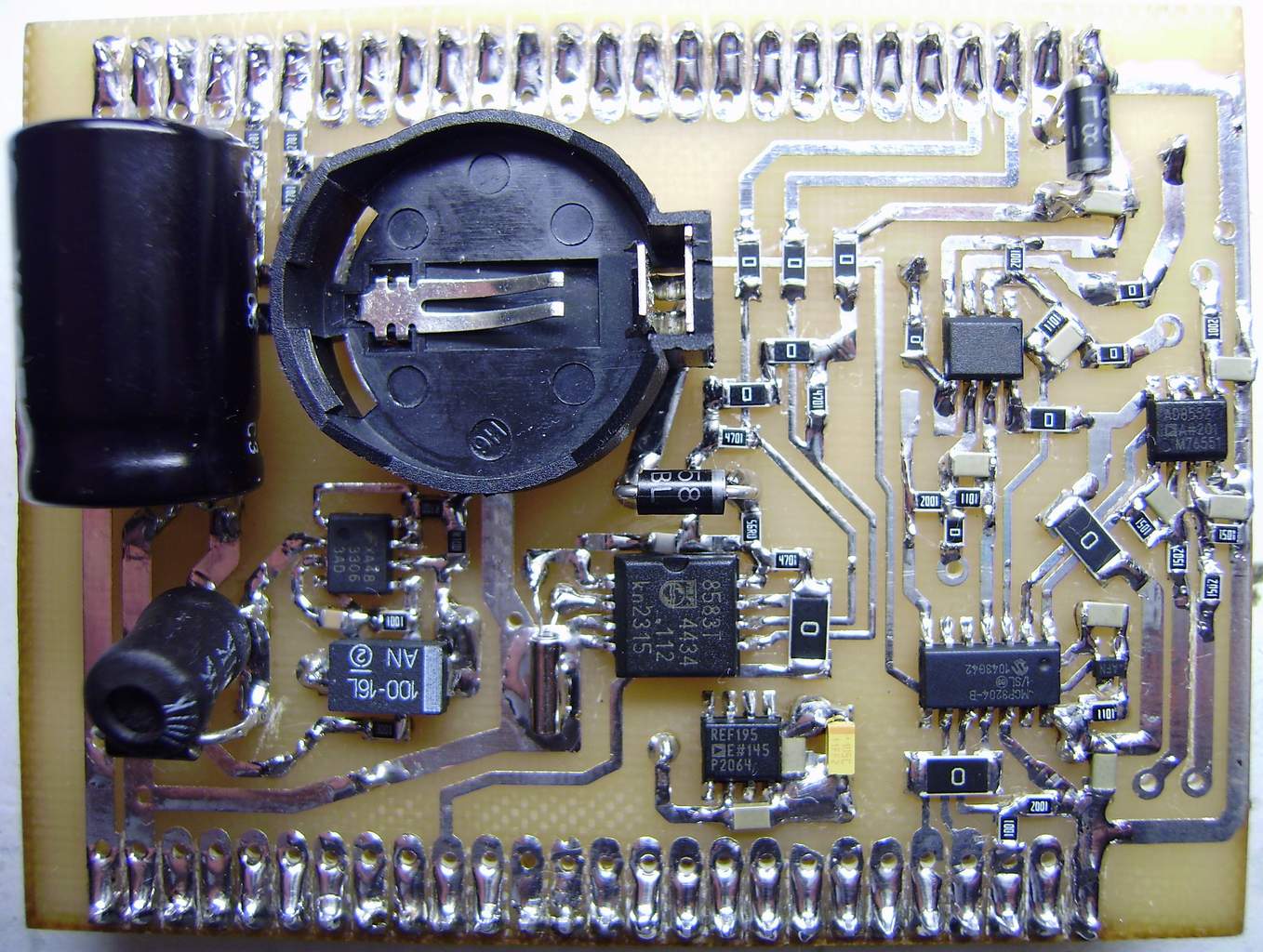
Wiring diagram corresponds to circuit the Clicks ADC and RTC.

accent is made on high measurement accuracy and ease of execution.

and is intended for the intelligent charger, charge current from 0 to 40 A, with accuracy 0.25A, voltage 0 to 40V, with accuracy 0.01V

 http://www.libstock.com/projects/view/647/battery-charger-discharge-on-atmega16a-with-lcd-2x16-dc-dc-converter-on-smps-controller-tl494-and-current-sensor-acs758

1. RTC on PCF8583T
2. ADC on MCP3204-B
3. two AD8552
4. REF 4.096v on MAX6138bexr41, out =4,0972 V* (REF for MCP3204-B)
5. pulse converter on MC33063, out =5,02 V* (power supply MikroMedia for ATmega)
6. linear regulator on REF195E, out =5,0035 V* (power supply ADC and operational Amplifiers)

*the measurements were performed APPA-505

ALSO FROM THIS AUTHOR

DC Fan speed control on ATtiny13 and DS18B20

5

Control of fan speed depending on the temperature

[Learn More]

Bootloader for ATmega128A 16MHz 19200bps via UART1

5

fast bootloader for ATmega128A (or ATmega128-16AU) 16MHz 19200bps via UART1, programming using the program AVRPROG, press the reset and start the program AvrProg, for two seconds. FUSE bit set boot from address 0xF800, BOOTSZ0 = 1, BOOTSZ1 = 0.

[Learn More]

The 6th version of the battery Charger/discharge up to 50A

0

Programmable synchronous step-down regulator, Based on: ATmega1284 with LCD 4x20, Keypad 4x4, ADC MCP3204, DAC DAC8830, ACS758xCB-050B, TL494, IR2184, RTC PCF8583, DS18B20 and USB UART FT232RL.

[Learn More]