TOP Contributors

  1. MIKROE (2784 codes)
  2. Alcides Ramos (405 codes)
  3. Shawon Shahryiar (307 codes)
  4. jm_palomino (133 codes)
  5. Bugz Bensce (97 codes)
  6. S P (73 codes)
  7. dany (71 codes)
  8. MikroBUS.NET Team (35 codes)
  9. NART SCHINACKOW (34 codes)
  10. Armstrong Subero (27 codes)

Most Downloaded

  1. Timer Calculator (141502 times)
  2. FAT32 Library (74401 times)
  3. Network Ethernet Library (58913 times)
  4. USB Device Library (48935 times)
  5. Network WiFi Library (44705 times)
  6. FT800 Library (44250 times)
  7. GSM click (30978 times)
  8. mikroSDK (29848 times)
  9. PID Library (27428 times)
  10. microSD click (27409 times)
Libstock prefers package manager

Package Manager

We strongly encourage users to use Package manager for sharing their code on Libstock website, because it boosts your efficiency and leaves the end user with no room for error. [more info]

< Back
Example

TE Connectivity Sensor Demo Example

Rating:

0

Author: MIKROE

Last Updated: 2022-02-14

Package Version: 1.0.0.0

Category: Sensors

Downloaded: 65 times

Not followed.

License: BSD 3-Clause "New" or "Revised" license  

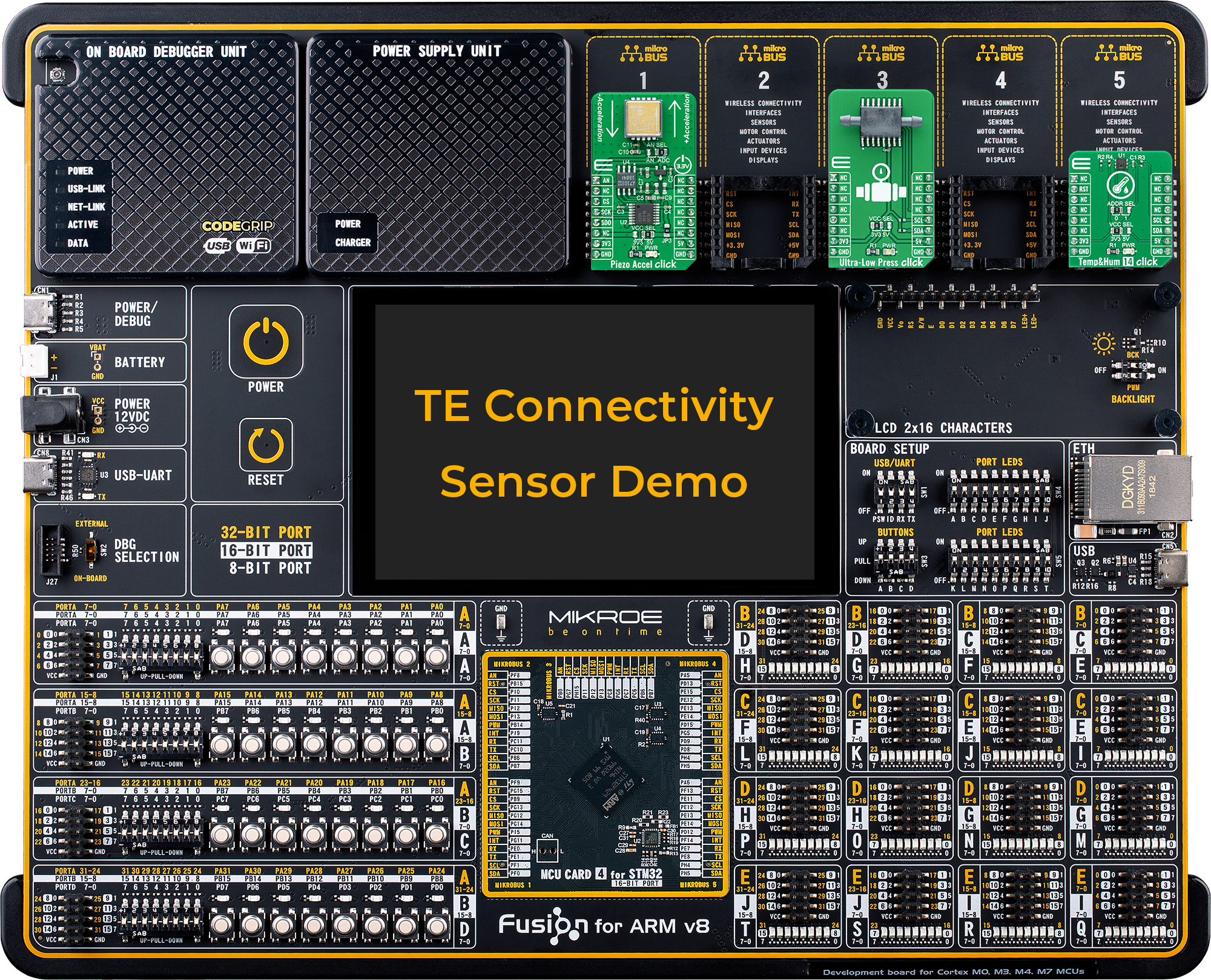
This example demonstrates the usage of several TE connectivity sensors such as Piezo Accel Click, Ultra-Low Press Click, Temp&amp;amp;Hum14 Click boards on a Fusion for ARM v8 development system.

No Abuse Reported

Do you want to subscribe in order to receive notifications regarding "TE Connectivity Sensor Demo Example" changes.

Do you want to unsubscribe in order to stop receiving notifications regarding "TE Connectivity Sensor Demo Example" changes.

Do you want to report abuse regarding "TE Connectivity Sensor Demo Example".

  • Information
  • Comments (0)
DOWNLOAD LINK RELATED COMPILER CONTAINS
mikroC AI for ARM
  • lib
  • src
  • exa
  • hlp
  • hex
  • sch
  • pcb
  • doc

Example Blog

TE Connectivity Sensor Demo app is a demonstration project of how MIKROE fully customizable development board, such as Fusion for ARM v8, can be used for evaluation or development purposes. This type of setup allows easy customization of the main microcontroller, display type, and size depending on the HMI application, as well as peripheral sensors and actuators.

Besides standardized and universal hardware connectors, MIKROE offers also standardized software packages for peripheral add-on boards. This allows users to easily switch between microcontrollers, even beyond one architecture, without any need to change the library or their projects. For example, starting a project with ARM Cortex-M0 and in 5-sec switch to Cortex-M7 MCU, or ever from ARM to PIC microcontrollers.

TE connectivity Demo Setup

TE connectivity Demo Setup

Hardware Setup

View full image

Required Hardware:

  1. Fusion for ARM v8
  2. MCU CARD for STM32 F407
  3. TFT Board 5” Resistive
  4. Piezo Accel Click – located on the mikroBUS 1
  5. Ultra-Low Press Click – located on the mikroBUS 3
  6. Temp&Hum 14 Click – located on the mikroBUS 5
 

This demonstration can be easily and quickly accessed on the remote Planet Debug via NECTO STUDIO IDE.

The demo project was written by using NECTO STUDIO IDE, mikroC AI for ARM compiler, mikroSDK 2.0, and several other MIKROE libraries. 

ALSO FROM THIS AUTHOR

6DOF IMU 14 Click

0

6DOF IMU 14 Click is a compact add-on board that contains a 6-axis MEMS motion tracking device combining a 3-axis gyroscope and a 3-axis accelerometer. This board features the ICM-42688-P, high precision 6-axis MEMS motion tracking device, from TDK InvenSense.

[Learn More]

Hall Current 9 Click

0

Hall Current 9 Click is a compact add-on board that contains the coreless current sensor corresponding to the safety standards. This board features the CQ3300, a high-speed response coreless current sensor using a Hall sensor that outputs the analog voltage proportional to the AC/DC from AKM Semiconductor.

[Learn More]

Button G click

1

Button G click is the simplest solution for adding a single pushbutton to your design. The button itself is transparent, 6.8mm in diameter and has a green LED backlight. When pressed, it sends an interrupt signal to the target board microcontroller. The backlight LED is controlled separately through the mikroBUSâ„¢ PWM pin.

[Learn More]