TOP Contributors

  1. MIKROE (2784 codes)
  2. Alcides Ramos (405 codes)
  3. Shawon Shahryiar (307 codes)
  4. jm_palomino (133 codes)
  5. Bugz Bensce (97 codes)
  6. S P (73 codes)
  7. dany (71 codes)
  8. MikroBUS.NET Team (35 codes)
  9. NART SCHINACKOW (34 codes)
  10. Armstrong Subero (27 codes)

Most Downloaded

  1. Timer Calculator (141327 times)
  2. FAT32 Library (74155 times)
  3. Network Ethernet Library (58738 times)
  4. USB Device Library (48834 times)
  5. Network WiFi Library (44544 times)
  6. FT800 Library (44126 times)
  7. GSM click (30857 times)
  8. mikroSDK (29699 times)
  9. PID Library (27359 times)
  10. microSD click (27273 times)
Libstock prefers package manager

Package Manager

We strongly encourage users to use Package manager for sharing their code on Libstock website, because it boosts your efficiency and leaves the end user with no room for error. [more info]

< Back
Project

Programmable Relay Timers (PIC)

Rating:

18

Author: MIKROE

Last Updated: 2016-02-18

Package Version: 1.0.0.1

Category: Timers (Real time clock)

Downloaded: 7320 times

Followed by: 3 users

License: MIT license  

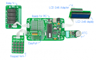
Build your own programmable timer relays using Ready for PIC, Keypad 4x4 board with EasyPull, RTC, Relay 4 and LCD 2x16 character display with adapter. Just load the demonstration project code and your device is ready to control 4 separate relays.

No Abuse Reported

Do you want to subscribe in order to receive notifications regarding "Programmable Relay Timers (PIC)" changes.

Do you want to unsubscribe in order to stop receiving notifications regarding "Programmable Relay Timers (PIC)" changes.

Do you want to report abuse regarding "Programmable Relay Timers (PIC)".

  • Information
  • Comments (1)

Project Blog

Figure 1 - Programmable Relay Timer project

Figure 1 - Programmable Relay Timer project

Programmable Relay Timer project connections

View full image

Following AVR version, we present your with PIC version of Programmable relay timers project. We have created a demonstrational software for all of our PIC compilers and prepared a special project kit which you can use to build your own programmable relay timers under a minute. Just connect Ready for PIC, Keypad 4x4 board with EasyPull, RTC, Relay 4 and LCD 2x16 character display with adapter and load demonstration project code and your device is ready to rock! It can control 4 separate relays.

Programmable Relay Timers (PIC) Video

Video Demonstration of the project

Watch on YouTube

  1. Using “D” key on keypad 4x4 board you can scroll through settings for each relay. You can change the ON and OFF times by positioning the cursor to the desired location and changing time values as you desire. Navigation, or moving the cursor is done using asterisk (*) for backward and sharp (#) key for forward.
  2. Press “C” key to display current time.
  3. Press “B” key to enter the mode for adjusting the current time value. Position the cursor over the desired location and change HH:MM:SS values to synchronize it with your local time. After you are done, press “B” again to save the newly set value.

Applications

Project has numerous applications. We only suggest several:

  1. Controlling garden sprinklers
  2. Turning ON/OFF home appliances (Coffee makers, toasters, TV sets, airconditioning, old washing mashines, etc.)
  3. Programming city or home fountains to turn on and off in the same time of the day
  4. Controling street lamps and home lights

We are sure that you will find much more possible applications. Don’t hesitate to send us photos of what you have built using this project kit.
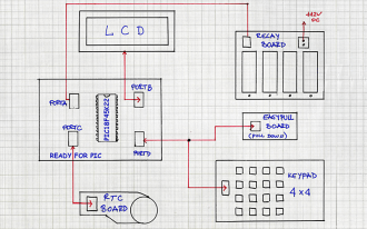
Figure 2 - Programmable Relay Timers schematics

Figure 2 - Programmable Relay Timers schematics

Connection schematics

View full image

Source code of this project is provided for free, so you can modify it to suit your needs. Since PIC18F45K22 comes preprogrammed with free UART Bootloader, you won’t have to spend a dollar more on external programmers. You can modify the project as much as you like, and expand this basic functionality with your own implementation ideas.

ALSO FROM THIS AUTHOR

Pressure 7 Click

0

Pressure 7 Click features an integrated digital barometric pressure and temperature sensor labeled as MS5837.

[Learn More]

Joystick click

0

Simple demonstration of using AS5013 chip. If joystick is moved, cross will move on GLCD folowing joystick's move. When joystick is pressed frame around cross will appear. Example demonstrates writing and reading from AS5013 chip.

[Learn More]

pH 2 Click

0

pH 2 Click is a compact add-on board used to determine the alkalinity or acidity of a sample. This board features the MCP607, a low-bias current Op Amp from Microchip, performing level shifting and high-input impedance buffering in a single-supply pH-electrode circuit.

[Learn More]