TOP Contributors

  1. MIKROE (2762 codes)
  2. Alcides Ramos (374 codes)
  3. Shawon Shahryiar (307 codes)
  4. jm_palomino (118 codes)
  5. Bugz Bensce (90 codes)
  6. S P (73 codes)
  7. dany (71 codes)
  8. MikroBUS.NET Team (35 codes)
  9. NART SCHINACKOW (34 codes)
  10. Armstrong Subero (27 codes)

Most Downloaded

  1. Timer Calculator (139248 times)
  2. FAT32 Library (71743 times)
  3. Network Ethernet Library (57115 times)
  4. USB Device Library (47428 times)
  5. Network WiFi Library (43082 times)
  6. FT800 Library (42403 times)
  7. GSM click (29835 times)
  8. mikroSDK (28073 times)
  9. PID Library (26885 times)
  10. microSD click (26198 times)
Libstock prefers package manager

Package Manager

We strongly encourage users to use Package manager for sharing their code on Libstock website, because it boosts your efficiency and leaves the end user with no room for error. [more info]

< Back
mikroSDK Library

GSM 2 click

Rating:

7

Author: MIKROE

Last Updated: 2018-03-13

Package Version: 2.0.0.1

mikroSDK Library: 1.0.0.0

Category: GSM/LTE

Downloaded: 21632 times

Followed by: 3 users

License: MIT license  

GSM2 Click is a board in mikroBUSâ„¢ form factor which is a solution for adding GSM/GPRS communication layer to your device. It features Quectel M95 GSM/GPRS module which supports most GSM quad-band frequencies with 85.6 kbps GPRS data transfer.

No Abuse Reported

Do you want to subscribe in order to receive notifications regarding "GSM 2 click" changes.

Do you want to unsubscribe in order to stop receiving notifications regarding "GSM 2 click" changes.

Do you want to report abuse regarding "GSM 2 click".
  • mikroSDK Library 2.0.0.0
  • Comments (5)
DOWNLOAD LINK RELATED COMPILER CONTAINS
mikroBasic PRO for ARM
  • lib
  • src
  • exa
  • hlp
  • hex
  • sch
  • pcb
  • doc
mikroBasic PRO for AVR
  • lib
  • src
  • exa
  • hlp
  • hex
  • sch
  • pcb
  • doc
mikroBasic PRO for dsPIC30/33 & PIC24
  • lib
  • src
  • exa
  • hlp
  • hex
  • sch
  • pcb
  • doc
mikroBasic PRO for FT90x
  • lib
  • src
  • exa
  • hlp
  • hex
  • sch
  • pcb
  • doc
mikroBasic PRO for PIC
  • lib
  • src
  • exa
  • hlp
  • hex
  • sch
  • pcb
  • doc
mikroBasic PRO for PIC32
  • lib
  • src
  • exa
  • hlp
  • hex
  • sch
  • pcb
  • doc
mikroC PRO for ARM
  • lib
  • src
  • exa
  • hlp
  • hex
  • sch
  • pcb
  • doc
mikroC PRO for AVR
  • lib
  • src
  • exa
  • hlp
  • hex
  • sch
  • pcb
  • doc
mikroC PRO for dsPIC30/33 & PIC24
  • lib
  • src
  • exa
  • hlp
  • hex
  • sch
  • pcb
  • doc
mikroC PRO for FT90x
  • lib
  • src
  • exa
  • hlp
  • hex
  • sch
  • pcb
  • doc
mikroC PRO for PIC
  • lib
  • src
  • exa
  • hlp
  • hex
  • sch
  • pcb
  • doc
mikroC PRO for PIC32
  • lib
  • src
  • exa
  • hlp
  • hex
  • sch
  • pcb
  • doc
mikroPascal PRO for ARM
  • lib
  • src
  • exa
  • hlp
  • hex
  • sch
  • pcb
  • doc
mikroPascal PRO for AVR
  • lib
  • src
  • exa
  • hlp
  • hex
  • sch
  • pcb
  • doc
mikroPascal PRO for dsPIC30/33 & PIC24
  • lib
  • src
  • exa
  • hlp
  • hex
  • sch
  • pcb
  • doc
mikroPascal PRO for FT90x
  • lib
  • src
  • exa
  • hlp
  • hex
  • sch
  • pcb
  • doc
mikroPascal PRO for PIC
  • lib
  • src
  • exa
  • hlp
  • hex
  • sch
  • pcb
  • doc
mikroPascal PRO for PIC32
  • lib
  • src
  • exa
  • hlp
  • hex
  • sch
  • pcb
  • doc

mikroSDK Library Blog

GSM 2 click

GSM 2 click

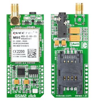
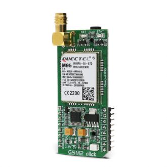
Native view of the GSM 2 click board.

View full image
GSM2 click

GSM2 click

Front and back side appearance of the GSM2 click Board.

View full image

Library Description

The library carries a generic command parser adopted for AT command based modules. Generic parser.

Key functions:

gsm2_cmdSingle - Sends a provided command to the module.

gsm2_setHandler - Handler assignation to the provided command.

gsm2_modulePower - Turns on the module.

Examples Description

The example demo application waits for the cal, and after the call is received the parser will get hang up.

This code snippet shows how a generic parser should be properly initialized. Before the initialization, the module must be turned on, and in addition to this, the hardware flow control should also be turned on.

Commands:

  • The first command negotiates the baud rate with the module.
  • The second command turns the echo off.
  • The third command enables hardware flow control - necessary in case of UART polling.
  • The fourth command sets up default message format.
     
void applicationInit()
{
// MODULE POWER ON
 gsm2_hfcEnable( true );
 gsm2_modulePower( true );

// MODULE INIT
 gsm2_cmdSingle( "AT" );
 gsm2_cmdSingle( "ATE0" );
 gsm2_cmdSingle( "AT+IFC=2,2" );
 gsm2_cmdSingle( "AT+CMGF=1" );
}

Along with the demo application, timer initialization functions are provided. Note that the timer is configured according to the default development system and MCUs, changing the system or MCU may require an update of timer init and timer ISR functions.

Other mikroE Libraries used in the example:

  • String
  • Conversion

Additional notes and information

Depending on the development board you are using, you may need USB UART click,  USB UART 2 click or RS232 click to connect to your PC, for development systems with no UART to USB interface available on the board. The terminal available in all MikroElektronika compilers, or any other terminal application of your choice, can be used to read the message.


ALSO FROM THIS AUTHOR

DAQ 3 Click

0

DAQ 3 Click is a compact add-on board representing a precision data acquisition solution. This board features the ADAQ4003, fast and precise μModule precision data acquisition (DAQ) signal chain solution from Analog Devices. Using SIP technology, the ADAQ4003 reduces end system component count by combining multiple standard signal processing and conditioning blocks into a single device. These blocks include a high-resolution 18-bit, 2 MSPS successive approximation register ADC, fully differential ADC driver amplifier, and a stable reference buffer along with selectable gain options. This Click board™ is suitable for process control and machine automation applications, as automatic test equipment, digital control loops, and more.

[Learn More]

Buck-Boost Click

0

Buck-Boost Click™ features LTC3129-1, a buck-boost DC/DC conversion integrated circuit. The Click supports a wide input voltage range and can output eight discrete regulated output voltage levels, selectable by the digital output voltage selection pins, ranging from 2.5V to 15V.

[Learn More]

8x8 G click

5

8x8 clicks are 8x8 LED matrix displays in form of add-on boards in mikroBUS form factor. Boards feature MAX7219 8-digit LED display driver module as well as 64 LED diodes.

[Learn More]