
We strongly encourage users to use Package manager for sharing their code on Libstock website, because it boosts your efficiency and leaves the end user with no room for error. [more info]

Rating:
Author: Petar Timotijević
Last Updated: 2013-06-07
Package Version: 6.0.0.0
Example: 1.0.0.0
Category: Measurement
Downloaded: 2200 times
Followed by: 1 user
License: MIT license
ADC Input: 0-5V Output 2x16 LCD: 0-5V
ADC Input: 0-5V Output 2x16 LCD: 0-20V
ADC Input: 0-5V Output 2x16 LCD: -25A 0 +25A
ADC Input: -10V 0 +10V Output 2x16 LCD: 0-5V
ADC Input: -2,5V 0 +2,5V Output 2x16 LCD: -2,5V 0 +2,5V
ADC Input: -20V 0 +20V Output 2x16 LCD: 0-5V
ADC Input: -5V 0 +5V Output 2x16 LCD: 0-5V
Do you want to subscribe in order to receive notifications regarding "ADC Code Examples for Various Offset Ranges" changes.
Do you want to unsubscribe in order to stop receiving notifications regarding "ADC Code Examples for Various Offset Ranges" changes.
Do you want to report abuse regarding "ADC Code Examples for Various Offset Ranges".
| DOWNLOAD LINK | RELATED COMPILER | CONTAINS |
|---|---|---|
| 1370610090_adc_code_example_mikroc_pic.RAR [1.39MB] | mikroC PRO for PIC |
|

Example for ACS712-20 20A Hall Sensor from -20A to +20A Step 1 (ADC 1-1023)
View full image
Example for ACS712-20 20A Hall Sensor from -20A to +20A Step 256 (ADC 1-1023)
View full image
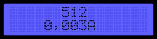
Example for ACS712-20 20A Hall Sensor from -20A to +20A Step 512 (ADC 1-1023)
View full image
Example for ACS712-20 20A Hall Sensor from -20A to +20A Step 768 (ADC 1-1023)
View full image
Example for ACS712-20 20A Hall Sensor from -20A to +20A Step 1023 (ADC 1-1023)
View full imageFor each ADC Offset use appropriate voltage divider or OpAmp configuration to ensure ADC input in 0-5V range.
Each example have LCD screenshots, and can be adjusted for other values.
7 ADC Examples :
ADC Input: 0-5V Output 2x16 LCD: 0-5V
ADC Input: 0-5V Output 2x16 LCD: 0-20V (Example for voltmeter 0-20V)
ADC Input: 0-5V Output 2x16 LCD: -25A 0 +25A (Example for ACS712-20 20A Hall sensor)
ADC Input: -10V 0 +10V Output 2x16 LCD: 0-5V
ADC Input: -2,5V 0 +2,5V Output 2x16 LCD: -2,5V 0 +2,5V
ADC Input: -20V 0 +20V Output 2x16 LCD: 0-5V
ADC Input: -5V 0 +5V Output 2x16 LCD: 0-5V


