We strongly encourage users to use Package manager for sharing their code on Libstock website, because it boosts your efficiency and leaves the end user with no room for error. [more info]

Rating:
Author: v.savic
Last Updated: 2016-02-19
Package Version: 1.0.0.0
Example: 1.0.0.0
Category: Motor Control
Downloaded: 2059 times
Followed by: 1 user
License: MIT license
This example is related to simple PWM generator for standard DC motor.
Example is base on my previous example related to Injection System Behavior
Do you want to subscribe in order to receive notifications regarding "PWM Generator for Standard DC Motors" changes.
Do you want to unsubscribe in order to stop receiving notifications regarding "PWM Generator for Standard DC Motors" changes.
Do you want to report abuse regarding "PWM Generator for Standard DC Motors".
| DOWNLOAD LINK | RELATED COMPILER | CONTAINS |
|---|---|---|
| 1377097149_pwm_generator_fo_mikroc_8051.zip [14.67KB] | mikroC PRO for 8051 |
|
This example is related to simple PWM generator for standard DC motor.
Complete example is based on my previous example related to Injection System Behavior.
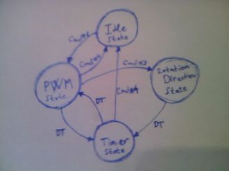
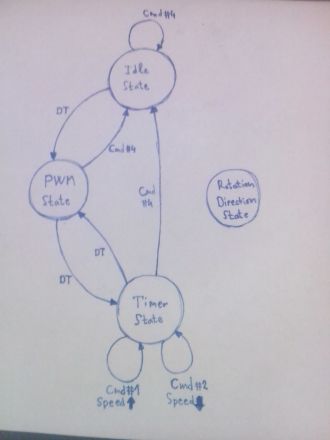
PWM modulation signal is generated by transitions through state machine states.
State machine has four states: Idle, PWM, Timer and Direction. Transition matrix has 17 bytes. x2Mode is used for state encoding.
Provided material for download contains two bin files related to different behavior of the system.
1. DCSpeedController.bin - rotation in one direction with speed regulation
2. DCSpeedDirectionController.bin - rotation in both direction with speed regulation
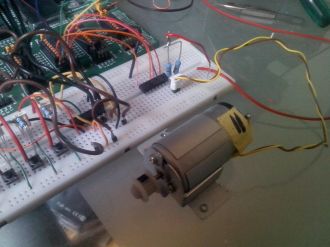
Electronics #1: beside priority encoder for external commands encoding, interface between 8051 MCU and DC motor is done over device driver BA12004 IC (replacement: ULN2XXX series - http://www.zilsel-invent.com/uln2xxx.xhtml motor driver kit). To create H-Bridge for bidirectional rotation, two additional resistors are used.
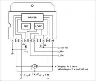
Electronics #2: beside priority encoder for external commands encoding, interface between 8051 MCU and DC motor is done over integrated H-Bridge chip BA6209.

Interface between DC Motor and MCU through Device Driver and H-Bridge
View full image
This state machine diagram is related to: DCSpeedDirectionController.bin - rotation in both direction with speed regulation
View full imageThis video is related to: DCSpeedDirectionController.bin - rotation in both direction with speed regulation
Watch on YouTube
This state machine diagram is related to bin file: DC Motor Example #2. In order for file to be used remove txt extension from the end of the file name.
View full image
Interface between 8051 MCU and DC motor is done over integrated H-Bridge chip BA6209 - from the old VHS VCR device ;-)
View full image