
We strongly encourage users to use Package manager for sharing their code on Libstock website, because it boosts your efficiency and leaves the end user with no room for error. [more info]

Rating:
Author: Philippe LE GUEN
Last Updated: 2016-02-21
Package Version: 1.0.0.0
Category: Measurement
Downloaded: 518 times
Followed by: 2 users
License: MIT license
If your generator has a VCF input, then you will be able to control the finely example using a microwave to contrôelur system equipped with a DAC (Digtal Analogic Converter), clear digital converter / analog.
Do you want to subscribe in order to receive notifications regarding "VCF Controller for function generator" changes.
Do you want to unsubscribe in order to stop receiving notifications regarding "VCF Controller for function generator" changes.
Do you want to report abuse regarding "VCF Controller for function generator".
| DOWNLOAD LINK | RELATED COMPILER | CONTAINS |
|---|---|---|
| 1401749084_contr__leur_vcf__mikroc_pic.zip [113.03KB] | mikroC PRO for PIC |
|


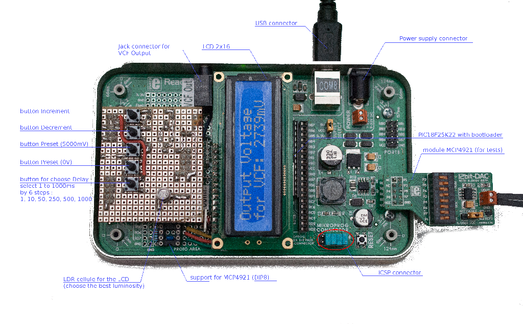
I used a 'Ready for PIC' board with a PIC18F25K22 and a 12-bit DAC (MCP4921)
View full imageIf your generator is equipped with a [VCF1] input, then you will be able to control it very finely, for example using a microcontroller system equipped with a DAC converter (Digtal Analogic Converter), a clear digital to analog converter.
It goes without saying that if your GBF does not have this VCF input, then this accessory will not be useful!
In fact the principle is to adjust the base frequency of its generator normally, with the buttons associated with it, then fine tune this frequency with the help of our VCF interface.
Usually, some micro-controllers already have such a converter internally ... yes, but on 10 bits, which gives us a resolution of 1023 different steps for example to change a voltage from 0V to + 5V. It is little, and not very precise for our generator.
We will give him a present! an external converter that converts on 12 bits, or 4095 no resolution. This changes everything, because to control the generator with its entry VCF, it needs precisely a voltage between 0V and + 5V, and there we will do it on 4095 steps (or steps ...).
I do not tell you comfort!
During tests on my generator, I realized that for a given frequency, when applying a VCF voltage of + 5V, this frequency had practically doubled! We can go from single to double (or almost ...) of our base frequency in steps of 1 thousandth of a volt! Do you see a little better interest?
Finally, this is not quite true, in fact if we divide 5000 (mV) by 4095, we get a coefficient of 1.221001221E0 very exactly. I use this coefficient for the calibration of the DAC in the software written in MikroC.
Programming
The processor comes pre-programmed with a bootloader from mikroElektronika, which allows me all the fantasies to change simply and very quickly (115200 baud / s) my program via the USB port. I used the software suite mikroC including all the necessary tools to carry out my project.
Be careful however, my software using 4680 bytes of the microcontroller ROM, you can not change it as you please without buying the license mikroC. The free version is limited to 2K bytes.
From project to design
I designed mine on a basis from MikroElektronika, the 'Ready for PIC' equipped with a PIC18F25K22 microcontroller (DIP28) running at the 32MHz clock rate, as you can say that it reacts quickly!
It is obviously possible to use other processors (in DIP28 or DIP40 and provided you review the option bits ...),
but it is with the PIC18F25K22 that I get the best operation.
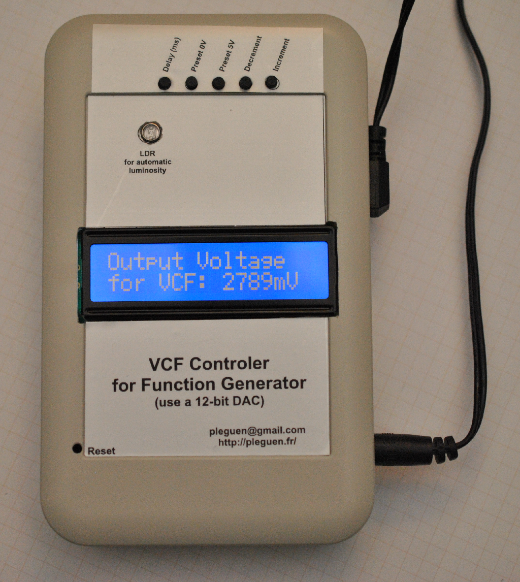
The 12-bit converter is a MCP4921 from Microchip. I added a backlit LCD 2x16 character display (whose brightness varies according to the ambient light thanks to an LDR cell and a PWM port), 5 sub-miniature pushbuttons which allow to adjust the output voltage of the DAC and the delay between each step, and as a bonus, as I was tired of adjusting my VCF voltage every morning when designing one of my personal applications, I planned to save the last value VCF in the internal memory of the microcontroller. Whenever you change the VCF value, it is immediately stored in memory. In case of power failure and even after reprogramming, the last value thus stored reappears immediately. Super comfortable!
The setting in box and the decoration of the front face
For the boxing of this new tool, I used the box distributed by mikroElektronika (Reference: MIKROE-1350), and performed cutting (sometimes risky ...) with the help of my trusty Dremel. The front panel was screen printed on aluminum self-adhesive paper from 3M (Reference: 3031) available from Selectonic, which I printed with my laser printer.
This gives it a more 'professional' presentation ...
The VCF controller is fully operational, it is visible on my website: http://pleguen.fr/
1. VCF : Voltage Control Frequency


