TOP Contributors

  1. MIKROE (2784 codes)
  2. Alcides Ramos (405 codes)
  3. Shawon Shahryiar (307 codes)
  4. jm_palomino (133 codes)
  5. Bugz Bensce (97 codes)
  6. S P (73 codes)
  7. dany (71 codes)
  8. MikroBUS.NET Team (35 codes)
  9. NART SCHINACKOW (34 codes)
  10. Armstrong Subero (27 codes)

Most Downloaded

  1. Timer Calculator (141955 times)
  2. FAT32 Library (75140 times)
  3. Network Ethernet Library (59420 times)
  4. USB Device Library (49409 times)
  5. Network WiFi Library (45227 times)
  6. FT800 Library (44808 times)
  7. GSM click (31355 times)
  8. mikroSDK (30364 times)
  9. microSD click (27741 times)
  10. PID Library (27595 times)
Libstock prefers package manager

Package Manager

We strongly encourage users to use Package manager for sharing their code on Libstock website, because it boosts your efficiency and leaves the end user with no room for error. [more info]

< Back
Project

Turn your Logic Analyzer into an Oscilloscope with AD9059

Rating:

5

Author: Michael CVM

Last Updated: 2016-02-21

Package Version: 1.0.0.0

Category: Measurement

Downloaded: 1307 times

Followed by: 1 user

License: MIT license  

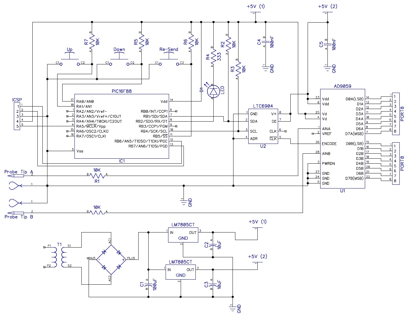
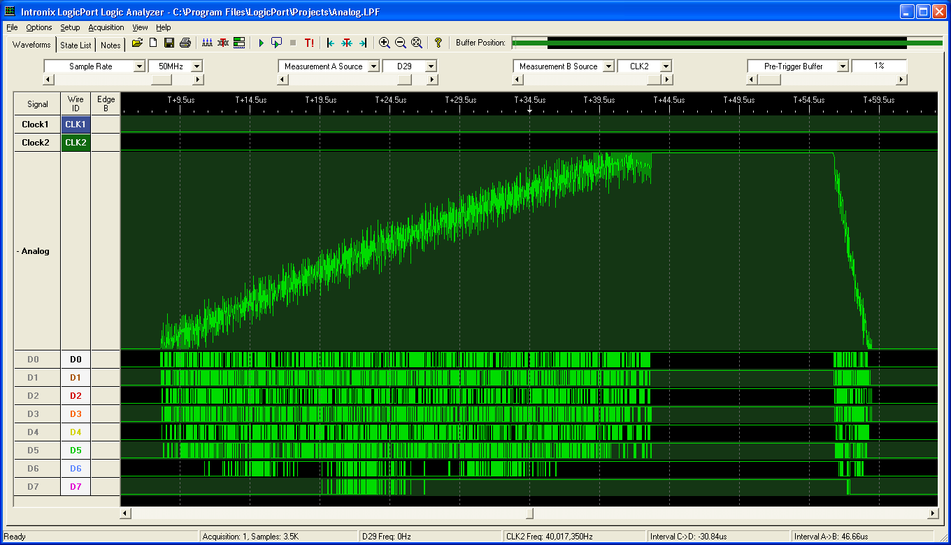
I have a Intronix LogicPort Logic Analyser, and the software has the capability to take digital inputs and display the input as analog.

I'm converting analog to digital using an AD9059 Dual 8-Bit, 60 MSPS A/D Converter.

For the clock source I'm using a LTC6904 Programmable Oscillator

The PIC sends through I2C the frequency to LTC6904

No Abuse Reported

Do you want to subscribe in order to receive notifications regarding "Turn your Logic Analyzer into an Oscilloscope with AD9059" changes.

Do you want to unsubscribe in order to stop receiving notifications regarding "Turn your Logic Analyzer into an Oscilloscope with AD9059" changes.

Do you want to report abuse regarding "Turn your Logic Analyzer into an Oscilloscope with AD9059".

  • Information
  • Comments (0)
DOWNLOAD LINK RELATED COMPILER CONTAINS
mikroC PRO for PIC
  • lib
  • src
  • exa
  • hlp
  • hex
  • sch
  • pcb
  • doc

Project Blog

Schematic

Schematic

Project Schematic

View full image
Analog display

Analog display

I took this pic a long time ago, I don't have an analog source to measure to make a better pic. Here I was measuring an ~27 KHz signal, but I set the sampling rate way too high, at 40MHz. I should have set it to 1 MHz (or so). If you set the samplin

View full image

RELATED CODES

LM75 temperature sensor with MAX7219 LED driver

0

LM75 i2c temperature sensor with MAX7219 LED driver. Output to 7 segment LED array. Program enables negative numbers, leading zero suppression, and decimal point out.

[Learn More]

DS18B20 temperature sensor with MCP23017 serial LCD

0

DS18B20 1-wire temperature sensor with MCP23017 i2c serial LCD. The system has leading zero suppression, negative numbers, and floating point outputs.

[Learn More]

Current sensor ACS712 - Calibration level zero

0

MCU ATmega 128A (or Atmega128-16AU) ADC MCP3204 LCD 16*2 Display Shield with Pushbuttons 5 buttons on one wire an internal ADC current sensor ACS712-ELCTR-20A-T Calibration level zero current sensor saved in internal EEPROM showing of current and voltage

[Learn More]