We strongly encourage users to use Package manager for sharing their code on Libstock website, because it boosts your efficiency and leaves the end user with no room for error. [more info]

Rating:
Author: Bitahwa Bindu
Last Updated: 2016-11-08
Package Version: 1.0.0.0
Category: Measurement
Downloaded: 3037 times
Followed by: 3 users
License: MIT license
The microcontroller reads the temperature every 10 s and compares it with the desired value to switch on a heater a fan to control the temperature.
Do you want to subscribe in order to receive notifications regarding "Automatic Temperature Control System using PIC Microcontroller" changes.
Do you want to unsubscribe in order to stop receiving notifications regarding "Automatic Temperature Control System using PIC Microcontroller" changes.
Do you want to report abuse regarding "Automatic Temperature Control System using PIC Microcontroller".
| DOWNLOAD LINK | RELATED COMPILER | CONTAINS |
|---|---|---|
| 1432228465_automatic_temper_mikroc_pic.zip [53.57KB] | mikroC PRO for PIC |
|
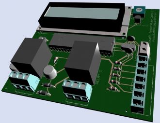
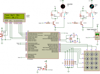
An automatic temperature control system has the ability to monitor and control the temperature of a specified space without human intervention. The primary purpose is to manage the temperature of a given area based on settings by a user of the system. This project uses a PIC microcontroller to automatically control the temperature of an area. This area could be a small plant, a house or any place or device that require a controlled temperature like an incubator (egg) for example. Figure 1 shows the block diagram of the system to be designed. The desired temperature setting is entered using a keypad. The temperature of the area is measured using an analog temperature sensor, the LM35 precision integrated-circuit temperature sensor is used for this. The microcontroller reads the temperature every 10 s and compares it with the desired value. If the desired value is higher than the measured value, then the heater is turned ON to heat the area. The heater is switched OFF once the desired temperature is reached. If on the other hand the measured value is higher than the desired value, then the fan is switched ON to cool off the area until the required temperature is reached. An LCD display shows the measured temperature continuously. Figure 2 shows the circuit diagram of the project. The LCD is connected to PORTC. The LM35 precision analog temperature sensor chip is connected to the analog input pin AN0 (RA0). A 3×4 keypad is connected to PORTB. The '*' key of the keypad is used to clear the value entered during the temperature setup and the '#' key is used to ENTER (save) the setting. The heater and the fan are controlled using transistors and relays connected to pins RD0 and RD1 of the microcontroller respectively. For more info please watch the video tutorial: Automatic Temperature Control System or visit our website: Automatic Temperature Control System


https://www.studentcompanion.co.za/automatic-temperature-control-system-using-pic-microcontroller-mikroc/
View full image