TOP Contributors

  1. MIKROE (2784 codes)
  2. Alcides Ramos (392 codes)
  3. Shawon Shahryiar (307 codes)
  4. jm_palomino (123 codes)
  5. Bugz Bensce (97 codes)
  6. S P (73 codes)
  7. dany (71 codes)
  8. MikroBUS.NET Team (35 codes)
  9. NART SCHINACKOW (34 codes)
  10. Armstrong Subero (27 codes)

Most Downloaded

  1. Timer Calculator (140544 times)
  2. FAT32 Library (73037 times)
  3. Network Ethernet Library (58043 times)
  4. USB Device Library (48215 times)
  5. Network WiFi Library (43826 times)
  6. FT800 Library (43295 times)
  7. GSM click (30359 times)
  8. mikroSDK (28990 times)
  9. PID Library (27116 times)
  10. microSD click (26721 times)
Libstock prefers package manager

Package Manager

We strongly encourage users to use Package manager for sharing their code on Libstock website, because it boosts your efficiency and leaves the end user with no room for error. [more info]

< Back
mikroSDK Library

PWM Click

Rating:

1

Author: MIKROE

Last Updated: 2019-04-20

Package Version: 1.0.0.2

mikroSDK Library: 1.0.0.0

Category: PWM

Downloaded: 6425 times

Followed by: 3 users

License: MIT license  

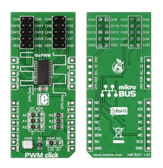
PWM click is a simple solution for controlling 16 PWM outputs through a single I2C interface. The click board carries the PCA9685PW IC. It is designed to use either a 3.3V or 5V power supply. The board also uses a LOW Output Enable Input pin (OE), which is in place of the default mikroBUS RST pin.

No Abuse Reported

Do you want to subscribe in order to receive notifications regarding "PWM Click" changes.

Do you want to unsubscribe in order to stop receiving notifications regarding "PWM Click" changes.

Do you want to report abuse regarding "PWM Click".
  • mikroSDK Library 2.0.0.0
  • Comments (9)
DOWNLOAD LINK RELATED COMPILER CONTAINS
mikroBasic PRO for ARM
  • lib
  • src
  • exa
  • hlp
  • hex
  • sch
  • pcb
  • doc
mikroBasic PRO for AVR
  • lib
  • src
  • exa
  • hlp
  • hex
  • sch
  • pcb
  • doc
mikroBasic PRO for dsPIC30/33 & PIC24
  • lib
  • src
  • exa
  • hlp
  • hex
  • sch
  • pcb
  • doc
mikroBasic PRO for FT90x
  • lib
  • src
  • exa
  • hlp
  • hex
  • sch
  • pcb
  • doc
mikroBasic PRO for PIC
  • lib
  • src
  • exa
  • hlp
  • hex
  • sch
  • pcb
  • doc
mikroBasic PRO for PIC32
  • lib
  • src
  • exa
  • hlp
  • hex
  • sch
  • pcb
  • doc
mikroC PRO for ARM
  • lib
  • src
  • exa
  • hlp
  • hex
  • sch
  • pcb
  • doc
mikroC PRO for AVR
  • lib
  • src
  • exa
  • hlp
  • hex
  • sch
  • pcb
  • doc
mikroC PRO for dsPIC30/33 & PIC24
  • lib
  • src
  • exa
  • hlp
  • hex
  • sch
  • pcb
  • doc
mikroC PRO for FT90x
  • lib
  • src
  • exa
  • hlp
  • hex
  • sch
  • pcb
  • doc
mikroC PRO for PIC
  • lib
  • src
  • exa
  • hlp
  • hex
  • sch
  • pcb
  • doc
mikroC PRO for PIC32
  • lib
  • src
  • exa
  • hlp
  • hex
  • sch
  • pcb
  • doc
mikroPascal PRO for ARM
  • lib
  • src
  • exa
  • hlp
  • hex
  • sch
  • pcb
  • doc
mikroPascal PRO for AVR
  • lib
  • src
  • exa
  • hlp
  • hex
  • sch
  • pcb
  • doc
mikroPascal PRO for dsPIC30/33 & PIC24
  • lib
  • src
  • exa
  • hlp
  • hex
  • sch
  • pcb
  • doc
mikroPascal PRO for FT90x
  • lib
  • src
  • exa
  • hlp
  • hex
  • sch
  • pcb
  • doc
mikroPascal PRO for PIC
  • lib
  • src
  • exa
  • hlp
  • hex
  • sch
  • pcb
  • doc
mikroPascal PRO for PIC32
  • lib
  • src
  • exa
  • hlp
  • hex
  • sch
  • pcb
  • doc

mikroSDK Library Blog

PWM Click

PWM Click

Front and back view of the PWM Click board designed in mikroBUS form factor.

View full image

Library Description

The library covers all the necessary functions that enables the usage of the PWM click board. It initializes and defines the I2C driver and drivers that offer a choice for controlling 16 PWM outputs through a single I2C interface. This library offer functions that allow the user to make controlled PWM output to each and every of 16 channels. It also allows for different configurations and prescaling. Library also offers generic read and write functions for aditional functionality.

Key functions:

  • pwm_devConfig( uint8_t allcall, uint8_t sub3, uint8_t sub2, uint8_t sub1, uint8_t sleep, uint8_t restart ) - Function is used to configure the device.
  • pwm_setChannel( uint8_t channId, uint8_t offset, uint8_t dutyCyc ) - Function is used to specific set channel output with data.
  • pwm_setAll( uint8_t dutyCyc ) - Function is used to set all channels output with data.

Examples description

The application is composed of the three sections :

  • System Initialization - Initializes GPIO, I2C and LOG structures, set RST pin as output.
  • Application Initialization - Initalizes I2C driver, enables output, configures device, sets prescaling, configures output and makes an initial log.
  • Application Task - (code snippet) - This is an example that shows some of the functions that PWM click has.
void applicationTask()
{
    uint16_t rawDc;
    uint8_t channId;
    uint8_t dutyCycle;
    channId = 0;
    mikrobus_logWrite( "Channel 0 false state  ", _LOG_LINE );
    pwm_channelState( channId, 0 );
    mikrobus_logWrite( "--------------------------", _LOG_LINE );
    Delay_ms( 2000 );
    
    mikrobus_logWrite( "Channel 0 set raw  ", _LOG_LINE );
    for ( rawDc = 0; rawDc < PWM_MAX_RESOLUTION; rawDc += 256 )
    {
        pwm_setChannelRaw( channId, 0, rawDc );
        mikrobus_logWrite( " >", _LOG_TEXT );
        Delay_ms( 500 );
    }
    mikrobus_logWrite( "", _LOG_LINE );
    mikrobus_logWrite( "--------------------------", _LOG_LINE );
    Delay_ms( 1000 );
    
    mikrobus_logWrite( "Channel 0 set  ", _LOG_LINE );
    for ( dutyCycle = 0; dutyCycle < 100; dutyCycle += 10 )
    {
        pwm_setChannel( channId, 0, dutyCycle );
        mikrobus_logWrite( " >", _LOG_TEXT );
        Delay_ms( 500 );
    }
    mikrobus_logWrite( "", _LOG_LINE );
    mikrobus_logWrite( "--------------------------", _LOG_LINE );
    Delay_ms( 1000 );
    
    mikrobus_logWrite( "All Channels raw set  ", _LOG_LINE );
    for ( rawDc = 0; rawDc < PWM_MAX_RESOLUTION; rawDc += 256 )
    {
        pwm_setAllRaw( rawDc );
        mikrobus_logWrite( " >", _LOG_TEXT );
        Delay_ms( 500 );
    }
    mikrobus_logWrite( "", _LOG_LINE );
    mikrobus_logWrite( "--------------------------", _LOG_LINE );
    Delay_ms( 1000 );
    
    mikrobus_logWrite( "All Channels set  ", _LOG_LINE );
    for ( dutyCycle = 0; dutyCycle < 100; dutyCycle += 10 )
    {
        pwm_setAll( dutyCycle );
        mikrobus_logWrite( " >", _LOG_TEXT );
        Delay_ms( 500 );
    }
    mikrobus_logWrite( "", _LOG_LINE );
    mikrobus_logWrite( "--------------------------", _LOG_LINE );
    Delay_ms( 1000 );
    
    mikrobus_logWrite( "All Channels false state  ", _LOG_LINE );
    pwm_allChannState( 0 );
    mikrobus_logWrite( "--------------------------", _LOG_LINE );
    Delay_ms( 2000 );
}

Other mikroE Libraries used in the example:

  • I2C
  • UART

Additional notes and informations

Depending on the development board you are using, you may need USB UART clickUSB UART 2 click or RS232 click to connect to your PC, for development systems with no UART to USB interface available on the board. The terminal available in all MikroElektronika compilers, or any other terminal application of your choice, can be used to read the message.
PWM Click Schematics

PWM Click Schematics

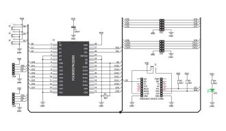
Schematics of the PWM click.

View full image

PWM click - example

PWM click is a simple solution for controlling 16 PWM outputs through a single I2C interface. You can use it to control anything from a simple LED strip to a complex robot with a multitude of moving parts. The click boardâ„¢ carries the PCA9685PW IC. The

Watch on YouTube

ALSO FROM THIS AUTHOR

7x10 R Click

0

7x10 R Click is a LED dot matrix display Click, which can be used to display graphics or letters in a very simple and easy way. The Click board has two LED dot matrix modules with 7x5 stylish, round, dot-like LED elements. These displays produce clean and uniform patterns since the elements are optically isolated from each other and there is no light bleeding between the adjacent LED cells. Additionally, turn-on and turn-off times of the matrix cells are optimized for a clean and fluid display performance, with no flickering or lag.

[Learn More]

UART 1-Wire Click

0

UART 1-Wire Click is used to convert standard UART or RS232 signals into 1-Wire® signals. Apart from other features such as the slew rate control for larger 1-Wire® busses, selectable data rate, an accurate self-calibrating time base, ESD protection and more, the main feature of the UART 1-Wire® Click, is that it manages all the sensitive signal timings involved in 1-Wire® communication, allowing rapid development of UART to 1-Wire® applications.

[Learn More]

Brushless 6 click

0

Brushless 6 click is designed to drive a three-phase sensorless, brushless motor, also known as the BLDC motor. The motor rotation is controlled by receiving driving commands via the incoming PWM signal.

[Learn More]