TOP Contributors

  1. MIKROE (2784 codes)
  2. Alcides Ramos (405 codes)
  3. Shawon Shahryiar (307 codes)
  4. jm_palomino (133 codes)
  5. Bugz Bensce (97 codes)
  6. S P (73 codes)
  7. dany (71 codes)
  8. MikroBUS.NET Team (35 codes)
  9. NART SCHINACKOW (34 codes)
  10. Armstrong Subero (27 codes)

Most Downloaded

  1. Timer Calculator (142118 times)
  2. FAT32 Library (75406 times)
  3. Network Ethernet Library (59567 times)
  4. USB Device Library (49551 times)
  5. Network WiFi Library (45359 times)
  6. FT800 Library (44994 times)
  7. GSM click (31486 times)
  8. mikroSDK (30567 times)
  9. microSD click (27892 times)
  10. PID Library (27635 times)
Libstock prefers package manager

Package Manager

We strongly encourage users to use Package manager for sharing their code on Libstock website, because it boosts your efficiency and leaves the end user with no room for error. [more info]

< Back
Example

USB I2C click

Rating:

5

Author: MIKROE

Last Updated: 2016-02-18

Package Version: 1.0.0.0

Example: 1.0.0.0

Category: USB

Downloaded: 3397 times

Followed by: 4 users

License: MIT license  

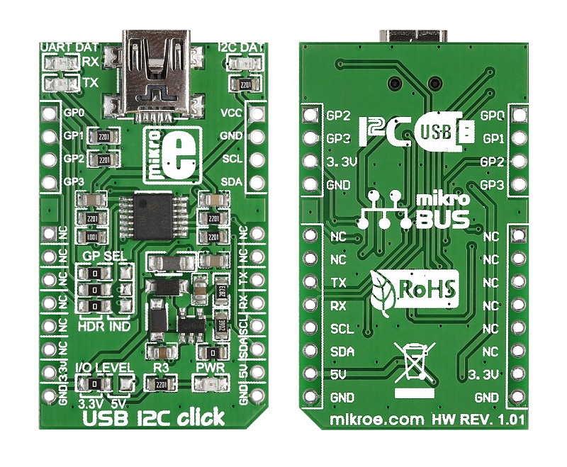
This example code demonstrates how USB I2C click can be used to control slave microcontroller via I2C. USB I2C click carries Microchip's MCP2221 chip. Click is designed to be supplied with 3.3V or 5V.

No Abuse Reported

Do you want to subscribe in order to receive notifications regarding "USB I2C click" changes.

Do you want to unsubscribe in order to stop receiving notifications regarding "USB I2C click" changes.

Do you want to report abuse regarding "USB I2C click".

  • Information
  • Comments (0)

Example Blog

USB I2C Click Board

USB I2C Click Board

Front and back side appearance of the USB I2C click Board.

View full image

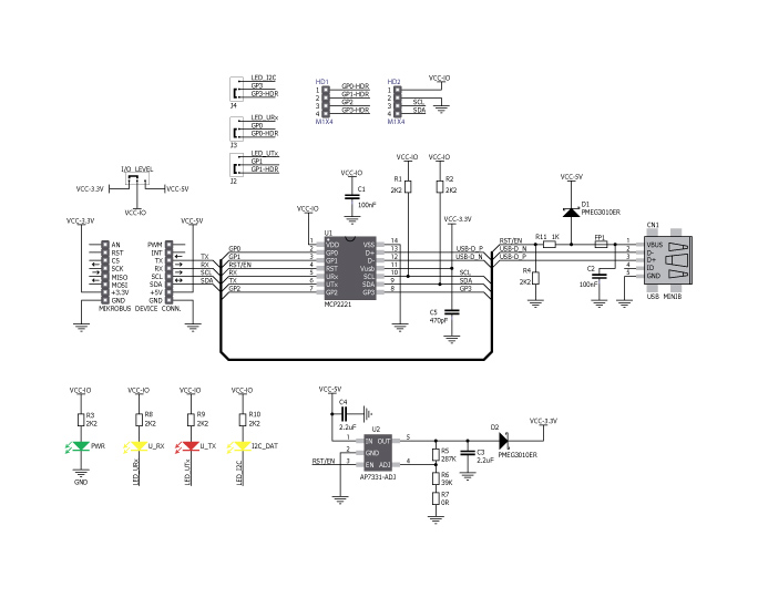
USB I2C click carries a MCP221 USB-to-UART/I2C converter. The board communicates with the target MCU through mikroBUS UART (RX, TX) or I2C (SCL, SDA) interfaces. In addition to mikroBUS, the edges of the board are lined with additional GPIO and I2C pins. It can use either a 3.3V or 5V logic levels.

Examples written for:

- EasyPIC v7 - PIC18F45K22

USB I2C click schematics

USB I2C click schematics

The schematics of the USB I2C click board.

View full image

ALSO FROM THIS AUTHOR

DAC 18 Click

0

DAC 18 Click is a compact add-on board for converting general-purpose input to PWM signals. This board features the DAC539G2-Q1, a 10-bit smart DAC from Texas Instruments. The board offers two key output channels: one for digital-to-analog conversion (OUT1) and the other for voltage-to-PWM conversion (OUT0) supporting triangle or sawtooth waveforms. It features an operational mode selection pin for I2C programming or standalone operation, along with nonvolatile memory for storing register settings. DAC 18 Click is ideal for automotive lighting systems and industrial environments requiring reliable signal conversion.

[Learn More]

Stepper 6 click

5

Stepper 6 click is the complete integrated bipolar step motor driver solution. It comes with the abundance of features that allow silent operation and optimal working conditions for the connected motor. A specialized integrated driver chip on this Click board far exceeds the capabilities of similar, commonly used step motor drivers.

[Learn More]

Buck 18 Click

0

Buck 18 Click is a compact add-on board for step-down voltage conversion in power-sensitive applications. This board features the MAXM38643, an ultra-low-IQ nanoPower buck module from Analog Devices, providing highly efficient voltage regulation with minimal power consumption. The board supports input voltages from 1.8V to 5.5V, converting them to output voltages between 0.7V and 3.3V. Users can manually adjust the output voltage through an onboard TRIM trimmer or digitally via the AD5171 digital potentiometer controlled through an I2C interface.

[Learn More]