TOP Contributors

  1. MIKROE (2784 codes)
  2. Alcides Ramos (405 codes)
  3. Shawon Shahryiar (307 codes)
  4. jm_palomino (133 codes)
  5. Bugz Bensce (97 codes)
  6. S P (73 codes)
  7. dany (71 codes)
  8. MikroBUS.NET Team (35 codes)
  9. NART SCHINACKOW (34 codes)
  10. Armstrong Subero (27 codes)

Most Downloaded

  1. Timer Calculator (141823 times)
  2. FAT32 Library (74955 times)
  3. Network Ethernet Library (59313 times)
  4. USB Device Library (49307 times)
  5. Network WiFi Library (45106 times)
  6. FT800 Library (44675 times)
  7. GSM click (31287 times)
  8. mikroSDK (30214 times)
  9. microSD click (27663 times)
  10. PID Library (27563 times)
Libstock prefers package manager

Package Manager

We strongly encourage users to use Package manager for sharing their code on Libstock website, because it boosts your efficiency and leaves the end user with no room for error. [more info]

< Back
mikroSDK Library

Charger click

Rating:

2

Author: MIKROE

Last Updated: 2019-05-23

Package Version: 1.0.0.1

mikroSDK Library: 1.0.0.0

Category: Battery Charger

Downloaded: 6252 times

Followed by: 4 users

License: MIT license  

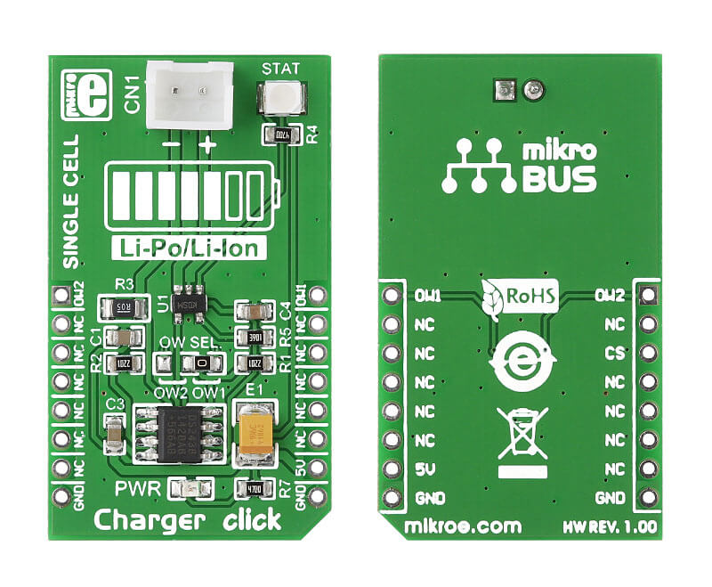
Charger click carries both a battery charger controller and a battery charge monitor. The smaller chip is MCP73831, a single-cell Li-Ion and Li-Polymer charge management controller. The larger IC is DS2438, a smart battery monitor. The monitor communicates with the MCU through a 1-Wire interface. The click is designed to use a 5V power supply.

No Abuse Reported

Do you want to subscribe in order to receive notifications regarding "Charger click" changes.

Do you want to unsubscribe in order to stop receiving notifications regarding "Charger click" changes.

Do you want to report abuse regarding "Charger click".

  • mikroSDK Library 2.0.0.0
  • Comments (2)
DOWNLOAD LINK RELATED COMPILER CONTAINS
mikroBasic PRO for ARM
  • lib
  • src
  • exa
  • hlp
  • hex
  • sch
  • pcb
  • doc
mikroBasic PRO for AVR
  • lib
  • src
  • exa
  • hlp
  • hex
  • sch
  • pcb
  • doc
mikroBasic PRO for dsPIC30/33 & PIC24
  • lib
  • src
  • exa
  • hlp
  • hex
  • sch
  • pcb
  • doc
mikroBasic PRO for FT90x
  • lib
  • src
  • exa
  • hlp
  • hex
  • sch
  • pcb
  • doc
mikroBasic PRO for PIC
  • lib
  • src
  • exa
  • hlp
  • hex
  • sch
  • pcb
  • doc
mikroBasic PRO for PIC32
  • lib
  • src
  • exa
  • hlp
  • hex
  • sch
  • pcb
  • doc
mikroC PRO for ARM
  • lib
  • src
  • exa
  • hlp
  • hex
  • sch
  • pcb
  • doc
mikroC PRO for AVR
  • lib
  • src
  • exa
  • hlp
  • hex
  • sch
  • pcb
  • doc
mikroC PRO for dsPIC30/33 & PIC24
  • lib
  • src
  • exa
  • hlp
  • hex
  • sch
  • pcb
  • doc
mikroC PRO for FT90x
  • lib
  • src
  • exa
  • hlp
  • hex
  • sch
  • pcb
  • doc
mikroC PRO for PIC
  • lib
  • src
  • exa
  • hlp
  • hex
  • sch
  • pcb
  • doc
mikroC PRO for PIC32
  • lib
  • src
  • exa
  • hlp
  • hex
  • sch
  • pcb
  • doc
mikroPascal PRO for ARM
  • lib
  • src
  • exa
  • hlp
  • hex
  • sch
  • pcb
  • doc
mikroPascal PRO for AVR
  • lib
  • src
  • exa
  • hlp
  • hex
  • sch
  • pcb
  • doc
mikroPascal PRO for dsPIC30/33 & PIC24
  • lib
  • src
  • exa
  • hlp
  • hex
  • sch
  • pcb
  • doc
mikroPascal PRO for FT90x
  • lib
  • src
  • exa
  • hlp
  • hex
  • sch
  • pcb
  • doc
mikroPascal PRO for PIC
  • lib
  • src
  • exa
  • hlp
  • hex
  • sch
  • pcb
  • doc
mikroPascal PRO for PIC32
  • lib
  • src
  • exa
  • hlp
  • hex
  • sch
  • pcb
  • doc

mikroSDK Library Blog

Charger Click Board

Charger Click Board

Front and back view of Charger Click board designed in mikroBUS form factor.

View full image

Library Description

The library covers all the necessary functions to control Charger click board. The library performs the communication with the device via 1-Wire protocol by writing to registers and by reading from registers.

Key functions:

  • void  charger_gpioDriverInit (T_CHARGER_P gpioObj) - Function initializes GPIO driver for the desired MIKROBUS1.

Examples description

The application is composed of the three sections :

  • System Initialization - Initializes GPIO structures and start to write log.
  • Application Initialization - Initialization driver enables - GPIO, and start One Wire communication, also write log.
  • Application Task - This is an example which demonstrates the use of Charger click board. Charger click communicates with register via One Wire protocol by the write to register and read from the register and display charger information from the DS2438 Smart Battery Monitor. Results are being sent to the Usart Terminal where you can track their changes. All data logs write on USB uart changes for every 1 sec.
void applicationTask()
{
    charger_getBatteryVoltage();
    Delay_100ms();

    mikrobus_logWrite( " Battery Voltage  : ", _LOG_TEXT );
    FloatToStr( batteryVoltage, logText );
    mikrobus_logWrite( logText, _LOG_TEXT );
    mikrobus_logWrite( " V", _LOG_LINE );

    mikrobus_logWrite( " Charger Current  : ", _LOG_TEXT );
    FloatToStr( chargerCurrent, logText );
    mikrobus_logWrite( logText, _LOG_TEXT );
    mikrobus_logWrite( " mA", _LOG_LINE );

    charger_getBatteryCapacity();
    Delay_100ms();

    mikrobus_logWrite( " Charger Capacity : ", _LOG_TEXT );
    FloatToStr( chargerCapacity, logText );
    mikrobus_logWrite( logText, _LOG_TEXT );
    mikrobus_logWrite( " mAhr", _LOG_LINE );

    mikrobus_logWrite( "---------------------------------", _LOG_LINE );
    Delay_1sec();
}

Additional Functions :

  • void charger_start() - Start and init DS2438 Smart Battery Monitor.
  • void charger_getBatteryVoltage() - Read sensor data for battery voltage and charger current.
  • void charger_getBatteryCapacity() - Read sensor data for charger capacity.
  • void charger_getBatteryLifetime() - Read sensor data for lifetime charge capacity.

Other mikroE Libraries used in the example:

  • One_Wire
  • UART​
  • Conversion

Additional notes and informations

Depending on the development board you are using, you may need USB UART clickUSB UART 2 click or RS232 click to connect to your PC, for development systems with no UART to USB interface available on the board. The terminal available in all MikroElektronika compilers, or any other terminal application of your choice, can be used to read the message.

ALSO FROM THIS AUTHOR

DIGI POT click

0

This program demonstrates the usage of single channel Digital Potentiometer (MCP4161) with 8 bit resolution. Voltage derived from PW pin is read by MCU's ADC. Scaled value is then displayed at PORTD LEDs. User can increase or decrease resitance by pressing buttons RB2 and RB3.&amp;lt;br/&amp;gt;

[Learn More]

BM78 Click

0

BM78 Click is a compact add-on board designed to integrate dual-mode Bluetooth wireless capability into various projects. This board features the BM78, a fully certified 2.4GHz Bluetooth (BR/EDR/LE) wireless module from Microchip. The BM78 module includes an on-board Bluetooth stack, power management subsystem, 2.4GHz transceiver, and RF power amplifier. It supports GAP, SDP, SPP, and GATT profiles, with data transfer facilitated through transparent UART mode. It features a MODE SEL switch for operational modes, a reset pin, status indicators, a software power button, and a WAKE button.

[Learn More]

DAC 8 click

5

DAC 8 Click is a compact add-on board that contains a fully-featured, general-purpose voltage-output digital-to-analog converter. This board features the DAC8554IPWR, a 16-bit QUAD channel voltage-output digital to analog converter from Texas Instruments.

[Learn More]