TOP Contributors

  1. MIKROE (2784 codes)
  2. Alcides Ramos (405 codes)
  3. Shawon Shahryiar (307 codes)
  4. jm_palomino (133 codes)
  5. Bugz Bensce (97 codes)
  6. S P (73 codes)
  7. dany (71 codes)
  8. MikroBUS.NET Team (35 codes)
  9. NART SCHINACKOW (34 codes)
  10. Armstrong Subero (27 codes)

Most Downloaded

  1. Timer Calculator (141178 times)
  2. FAT32 Library (73992 times)
  3. Network Ethernet Library (58601 times)
  4. USB Device Library (48756 times)
  5. Network WiFi Library (44452 times)
  6. FT800 Library (44025 times)
  7. GSM click (30784 times)
  8. mikroSDK (29510 times)
  9. PID Library (27332 times)
  10. microSD click (27188 times)
Libstock prefers package manager

Package Manager

We strongly encourage users to use Package manager for sharing their code on Libstock website, because it boosts your efficiency and leaves the end user with no room for error. [more info]

< Back
mikroSDK Library

VREG click

Rating:

1

Author: MIKROE

Last Updated: 2019-04-22

Package Version: 1.0.0.1

mikroSDK Library: 1.0.0.0

Category: Linear

Downloaded: 5294 times

Not followed.

License: MIT license  

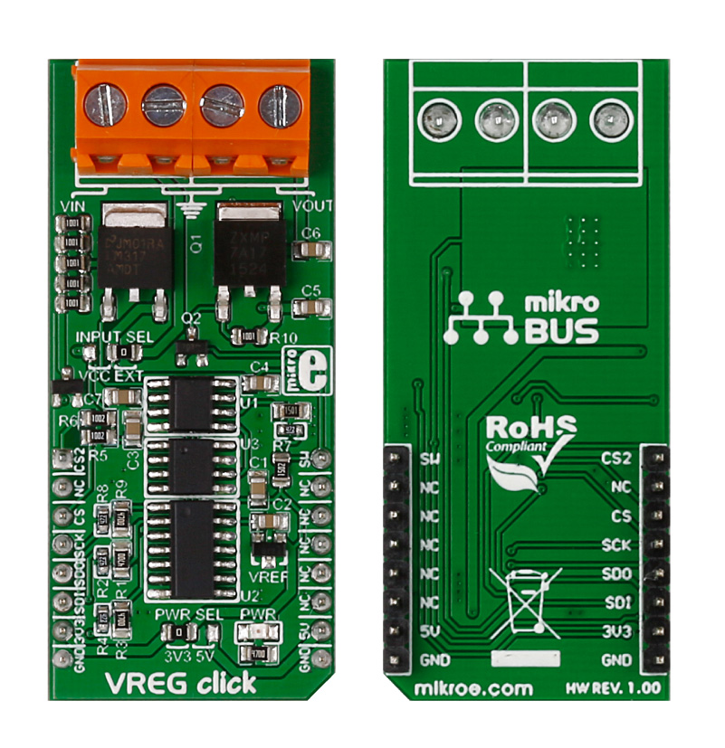
VREG click is a digitally controlled DC Voltage regulator in mikroBUS form factor. The design is based on the well-known LM317 circuit, with the addition of a 12-bit DAC, 12-bit ADC, and an Operational Amplifier. Two pairs of screw terminals serve as inputs and outputs.

No Abuse Reported

Do you want to subscribe in order to receive notifications regarding "VREG click" changes.

Do you want to unsubscribe in order to stop receiving notifications regarding "VREG click" changes.

Do you want to report abuse regarding "VREG click".

  • mikroSDK Library 2.0.0.0
  • Comments (2)
DOWNLOAD LINK RELATED COMPILER CONTAINS
mikroBasic PRO for ARM
  • lib
  • src
  • exa
  • hlp
  • hex
  • sch
  • pcb
  • doc
mikroBasic PRO for AVR
  • lib
  • src
  • exa
  • hlp
  • hex
  • sch
  • pcb
  • doc
mikroBasic PRO for dsPIC30/33 & PIC24
  • lib
  • src
  • exa
  • hlp
  • hex
  • sch
  • pcb
  • doc
mikroBasic PRO for FT90x
  • lib
  • src
  • exa
  • hlp
  • hex
  • sch
  • pcb
  • doc
mikroBasic PRO for PIC
  • lib
  • src
  • exa
  • hlp
  • hex
  • sch
  • pcb
  • doc
mikroBasic PRO for PIC32
  • lib
  • src
  • exa
  • hlp
  • hex
  • sch
  • pcb
  • doc
mikroC PRO for ARM
  • lib
  • src
  • exa
  • hlp
  • hex
  • sch
  • pcb
  • doc
mikroC PRO for AVR
  • lib
  • src
  • exa
  • hlp
  • hex
  • sch
  • pcb
  • doc
mikroC PRO for dsPIC30/33 & PIC24
  • lib
  • src
  • exa
  • hlp
  • hex
  • sch
  • pcb
  • doc
mikroC PRO for FT90x
  • lib
  • src
  • exa
  • hlp
  • hex
  • sch
  • pcb
  • doc
mikroC PRO for PIC
  • lib
  • src
  • exa
  • hlp
  • hex
  • sch
  • pcb
  • doc
mikroC PRO for PIC32
  • lib
  • src
  • exa
  • hlp
  • hex
  • sch
  • pcb
  • doc
mikroPascal PRO for ARM
  • lib
  • src
  • exa
  • hlp
  • hex
  • sch
  • pcb
  • doc
mikroPascal PRO for AVR
  • lib
  • src
  • exa
  • hlp
  • hex
  • sch
  • pcb
  • doc
mikroPascal PRO for dsPIC30/33 & PIC24
  • lib
  • src
  • exa
  • hlp
  • hex
  • sch
  • pcb
  • doc
mikroPascal PRO for FT90x
  • lib
  • src
  • exa
  • hlp
  • hex
  • sch
  • pcb
  • doc
mikroPascal PRO for PIC
  • lib
  • src
  • exa
  • hlp
  • hex
  • sch
  • pcb
  • doc
mikroPascal PRO for PIC32
  • lib
  • src
  • exa
  • hlp
  • hex
  • sch
  • pcb
  • doc

mikroSDK Library Blog

VREG click board

VREG click board

Front and back view of VREG click board

View full image

Library Description

The library covers all the necessary functions to control the VREG click board. The library performs the communication with the device via SPI driver by writing to registers and by reading from registers. The library has the function for sets DAC value and gets ADC value.

Key functions:

  • uint16_t vreg_getADC( uint8_t channel ) - Get ADC value function.
  • void vreg_setOutVoltage( uint16_t valueDAC ) - Set output voltage function.
  • void vreg_startMeasuring() - Start the measuring function.

Examples description

The application is composed of three sections:

  • System Initialization - Initializes GPIO, SPI and LOG structures, sets AN, CS and PWM pins as outputs.
  • Application Initialization -  Initialization driver enables - SPI, set output voltage and start to write log.
  • Application Task - (code snippet) This is an example which demonstrates the use of VREG click board. VREG click communicates with the device via SPI driver set DAC value and get ADC value. Results are being sent to the Usart Terminal where you can track their changes. All data logs write on usb uart changes for every 1 sec.
void applicationTask() 
{
    chReg = vreg_getADC( _VREG_CHANNEL_0 );
    WordToStr( chReg, logText );
    mikrobus_logWrite( " CH Reg  : ", _LOG_TEXT );
    mikrobus_logWrite( logText, _LOG_LINE );
    Delay_10ms();

    chIn = vreg_getADC( _VREG_CHANNEL_1 );
    WordToStr( chIn, logText );
    mikrobus_logWrite( " CH In   : ", _LOG_TEXT );
    mikrobus_logWrite( logText, _LOG_LINE );
    Delay_10ms();

    chOut = vreg_getADC( _VREG_CHANNEL_2 );
    WordToStr( chOut, logText );
    mikrobus_logWrite( " CH Out  : ", _LOG_TEXT );
    mikrobus_logWrite( logText, _LOG_LINE );
    mikrobus_logWrite( "-----------------", _LOG_LINE );
    Delay_1sec();
}        

Other mikroE Libraries used in the example:

  • SPI
  • UART​
  • Conversion

Additional notes and informations

Depending on the development board you are using, you may need USB UART clickUSB UART 2 click or RS232 click to connect to your PC, for development systems with no UART to USB interface available on the board. The terminal available in all MikroElektronika compilers, or any other terminal application of your choice, can be used to read the message

ALSO FROM THIS AUTHOR

SRAM 2 click

5

SRAM 2 Click is based on ANV32A62A SRAM memory from Anvo-Systems Dresden. It's a 64Kb serial SRAM with a non-volatile SONOS storage element included with each memory cell, organized as 8k words of 8 bits each. The devices are accessed by a two-wire bus. Up to 4 cascadable devices can share the common bus.

[Learn More]

MCP2518FD Click

0

MCP2518FD Click is a compact add-on board representing a complete CAN solution used as a control node in a CAN network. This board features the MCP2518FD, an external CAN FD controller with an SPI interface, and a high-speed CAN transceiver, the ATA6563, both from Microchip. The ATA6563, a low-level physical layer IC (PHY), provides a physical connection with the CAN bus itself, while the CAN controller MCP2518FD represents an interface between the MCU and the PHY. It features three operating modes with dedicated fail-safe features, remote wake-up via CAN, and ideally passive behavior when powered off on the CAN bus. This Click board™ is suitable for developing a wide range of automotive diagnostic applications, even on MCUs that do not natively support CAN interface.

[Learn More]

PWM Click

1

PWM click is a simple solution for controlling 16 PWM outputs through a single I2C interface. The click board carries the PCA9685PW IC. It is designed to use either a 3.3V or 5V power supply. The board also uses a LOW Output Enable Input pin (OE), which is in place of the default mikroBUS RST pin.

[Learn More]