TOP Contributors

  1. MIKROE (2784 codes)
  2. Alcides Ramos (405 codes)
  3. Shawon Shahryiar (307 codes)
  4. jm_palomino (133 codes)
  5. Bugz Bensce (97 codes)
  6. S P (73 codes)
  7. dany (71 codes)
  8. MikroBUS.NET Team (35 codes)
  9. NART SCHINACKOW (34 codes)
  10. Armstrong Subero (27 codes)

Most Downloaded

  1. Timer Calculator (141479 times)
  2. FAT32 Library (74335 times)
  3. Network Ethernet Library (58868 times)
  4. USB Device Library (48921 times)
  5. Network WiFi Library (44698 times)
  6. FT800 Library (44227 times)
  7. GSM click (30937 times)
  8. mikroSDK (29817 times)
  9. PID Library (27423 times)
  10. microSD click (27375 times)
Libstock prefers package manager

Package Manager

We strongly encourage users to use Package manager for sharing their code on Libstock website, because it boosts your efficiency and leaves the end user with no room for error. [more info]

< Back
mikroSDK Library

OLED Switch click

Rating:

1

Author: MIKROE

Last Updated: 2019-07-30

Package Version: 1.0.0.1

mikroSDK Library: 1.0.0.0

Category: OLED

Downloaded: 5265 times

Not followed.

License: MIT license  

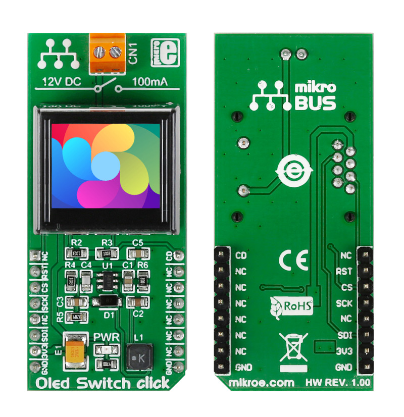
This board has a module that combines a button and a full color organic LED display, plus input/output screw terminals for connecting external electronics.

The mechanical button itself is nicely built, with a translucent black housing. When pressed, it gives satisfying tactile feedback.

No Abuse Reported

Do you want to subscribe in order to receive notifications regarding "OLED Switch click" changes.

Do you want to unsubscribe in order to stop receiving notifications regarding "OLED Switch click" changes.

Do you want to report abuse regarding "OLED Switch click".

  • mikroSDK Library 2.0.0.0
  • Comments (1)
DOWNLOAD LINK RELATED COMPILER CONTAINS
mikroBasic PRO for ARM
  • lib
  • src
  • exa
  • hlp
  • hex
  • sch
  • pcb
  • doc
mikroBasic PRO for AVR
  • lib
  • src
  • exa
  • hlp
  • hex
  • sch
  • pcb
  • doc
mikroBasic PRO for dsPIC30/33 & PIC24
  • lib
  • src
  • exa
  • hlp
  • hex
  • sch
  • pcb
  • doc
mikroBasic PRO for FT90x
  • lib
  • src
  • exa
  • hlp
  • hex
  • sch
  • pcb
  • doc
mikroBasic PRO for PIC
  • lib
  • src
  • exa
  • hlp
  • hex
  • sch
  • pcb
  • doc
mikroBasic PRO for PIC32
  • lib
  • src
  • exa
  • hlp
  • hex
  • sch
  • pcb
  • doc
mikroC PRO for ARM
  • lib
  • src
  • exa
  • hlp
  • hex
  • sch
  • pcb
  • doc
mikroC PRO for AVR
  • lib
  • src
  • exa
  • hlp
  • hex
  • sch
  • pcb
  • doc
mikroC PRO for dsPIC30/33 & PIC24
  • lib
  • src
  • exa
  • hlp
  • hex
  • sch
  • pcb
  • doc
mikroC PRO for FT90x
  • lib
  • src
  • exa
  • hlp
  • hex
  • sch
  • pcb
  • doc
mikroC PRO for PIC
  • lib
  • src
  • exa
  • hlp
  • hex
  • sch
  • pcb
  • doc
mikroC PRO for PIC32
  • lib
  • src
  • exa
  • hlp
  • hex
  • sch
  • pcb
  • doc
mikroPascal PRO for ARM
  • lib
  • src
  • exa
  • hlp
  • hex
  • sch
  • pcb
  • doc
mikroPascal PRO for AVR
  • lib
  • src
  • exa
  • hlp
  • hex
  • sch
  • pcb
  • doc
mikroPascal PRO for dsPIC30/33 & PIC24
  • lib
  • src
  • exa
  • hlp
  • hex
  • sch
  • pcb
  • doc
mikroPascal PRO for FT90x
  • lib
  • src
  • exa
  • hlp
  • hex
  • sch
  • pcb
  • doc
mikroPascal PRO for PIC
  • lib
  • src
  • exa
  • hlp
  • hex
  • sch
  • pcb
  • doc
mikroPascal PRO for PIC32
  • lib
  • src
  • exa
  • hlp
  • hex
  • sch
  • pcb
  • doc

mikroSDK Library Blog

OLED Switch click photo.

OLED Switch click photo.

Front and back images of OLED Switch click.

View full image

Library Description

The library covers all the necessary functions that enables the usage of the OLED Switch click.
It initializes and defines the SPI driver and drivers that offer a choice for
applying different types of settings and for drawing images on the OLED display.

Key functions:

  • void oledswitch_displayNormalMode() - Function is used to enable display normal mode.
  • void oledswitch_draw565Img( const uint8_t *img, uint16_t imgSize ) - Function takes a 565 formatted array and writes it to the OLED switch's memory.
  • void oledswitch_scrollingSetup( scroll_t setup ) - Function is used to set up the OLED Switch click for scrolling.

Examples description

The application is composed of three sections :

  • System Initialization - Initializes SPI module, LOG and GPIO structures, sets CS, RST and PWM pins as output and INT pin as output.
  • Application Initialization - Initalizes SPI driver and OLED Switch click, deacticates Scrolling and draws first image.
  • Application Task - Shows basic capabilities of OLED Switch click by changing color of the OLED screen once per second.
void applicationTask()
{
    oledswitch_draw565Img( _OLEDSWITCH_BMP_RED, _OLEDSWITCH_IMG_SIZE );
    Delay_ms( 1000 );
    oledswitch_draw565Img( _OLEDSWITCH_BMP_GREEN, _OLEDSWITCH_IMG_SIZE );
    Delay_ms( 1000 );
    oledswitch_draw565Img( _OLEDSWITCH_BMP_BLUE, _OLEDSWITCH_IMG_SIZE );
    Delay_ms( 1000 );
}

Other mikroE Libraries used in the example:

  • SPI
  • UART
  • Conversions

Additional notes and informations

Depending on the development board you are using, you may need USB UART clickUSB UART 2 click or RS232 click to connect to your PC, for development systems with no UART to USB interface available on the board. The terminal available in all MikroElektronika compilers, or any other terminal application of your choice, can be used to read the message.

ALSO FROM THIS AUTHOR

LIN Click

0

The LIN Click is a Click board™ that features the TLE7259-3GE, a LIN transceiver from Infineon Technologies, with integrated wake-up and protection features.

[Learn More]

Tilt 3 Click

0

Tilt 3 Click is a compact add-on board used for measuring the tilt in multiple axes in relation to an absolute level plane. This board features the DSBA1P, a tilt sensor switch that breaks the circuit when tilted to an angle from ±30° to ±60° from NKK Switches.

[Learn More]

DIGI POT 6 click

5

DIGI POT 6 Click features the MCP41HVX1 family of devices which have dual power rails (analog and digital). The analog power rail allows high voltage on the resistor network terminal pins. The analog voltage range is determined by the V+ and V- voltages.

[Learn More]