TOP Contributors

  1. MIKROE (2784 codes)
  2. Alcides Ramos (405 codes)
  3. Shawon Shahryiar (307 codes)
  4. jm_palomino (133 codes)
  5. Bugz Bensce (97 codes)
  6. S P (73 codes)
  7. dany (71 codes)
  8. MikroBUS.NET Team (35 codes)
  9. NART SCHINACKOW (34 codes)
  10. Armstrong Subero (27 codes)

Most Downloaded

  1. Timer Calculator (141361 times)
  2. FAT32 Library (74205 times)
  3. Network Ethernet Library (58776 times)
  4. USB Device Library (48854 times)
  5. Network WiFi Library (44564 times)
  6. FT800 Library (44149 times)
  7. GSM click (30883 times)
  8. mikroSDK (29739 times)
  9. PID Library (27372 times)
  10. microSD click (27309 times)
Libstock prefers package manager

Package Manager

We strongly encourage users to use Package manager for sharing their code on Libstock website, because it boosts your efficiency and leaves the end user with no room for error. [more info]

< Back
mikroSDK Library

ADC click

Rating:

0

Author: MIKROE

Last Updated: 2019-03-22

Package Version: 1.0.0.1

mikroSDK Library: 1.0.0.0

Category: ADC

Downloaded: 16407 times

Followed by: 2 users

License: MIT license  

Simple example which demonstrates working with the 4-Channel 12-bit A/D Converter (MCP3204) with SPI Serial Interface. The example shows how to measure analog inputs on Channels 0, 1, 2 and 3 and display the results on LCD.

No Abuse Reported

Do you want to subscribe in order to receive notifications regarding "ADC click" changes.

Do you want to unsubscribe in order to stop receiving notifications regarding "ADC click" changes.

Do you want to report abuse regarding "ADC click".

  • mikroSDK Library 2.0.0.0
  • Comments (2)
DOWNLOAD LINK RELATED COMPILER CONTAINS
mikroBasic PRO for ARM
  • lib
  • src
  • exa
  • hlp
  • hex
  • sch
  • pcb
  • doc
mikroBasic PRO for AVR
  • lib
  • src
  • exa
  • hlp
  • hex
  • sch
  • pcb
  • doc
mikroBasic PRO for dsPIC30/33 & PIC24
  • lib
  • src
  • exa
  • hlp
  • hex
  • sch
  • pcb
  • doc
mikroBasic PRO for FT90x
  • lib
  • src
  • exa
  • hlp
  • hex
  • sch
  • pcb
  • doc
mikroBasic PRO for PIC
  • lib
  • src
  • exa
  • hlp
  • hex
  • sch
  • pcb
  • doc
mikroBasic PRO for PIC32
  • lib
  • src
  • exa
  • hlp
  • hex
  • sch
  • pcb
  • doc
mikroC PRO for ARM
  • lib
  • src
  • exa
  • hlp
  • hex
  • sch
  • pcb
  • doc
mikroC PRO for AVR
  • lib
  • src
  • exa
  • hlp
  • hex
  • sch
  • pcb
  • doc
mikroC PRO for dsPIC30/33 & PIC24
  • lib
  • src
  • exa
  • hlp
  • hex
  • sch
  • pcb
  • doc
mikroC PRO for FT90x
  • lib
  • src
  • exa
  • hlp
  • hex
  • sch
  • pcb
  • doc
mikroC PRO for PIC
  • lib
  • src
  • exa
  • hlp
  • hex
  • sch
  • pcb
  • doc
mikroC PRO for PIC32
  • lib
  • src
  • exa
  • hlp
  • hex
  • sch
  • pcb
  • doc
mikroPascal PRO for ARM
  • lib
  • src
  • exa
  • hlp
  • hex
  • sch
  • pcb
  • doc
mikroPascal PRO for AVR
  • lib
  • src
  • exa
  • hlp
  • hex
  • sch
  • pcb
  • doc
mikroPascal PRO for dsPIC30/33 & PIC24
  • lib
  • src
  • exa
  • hlp
  • hex
  • sch
  • pcb
  • doc
mikroPascal PRO for FT90x
  • lib
  • src
  • exa
  • hlp
  • hex
  • sch
  • pcb
  • doc
mikroPascal PRO for PIC
  • lib
  • src
  • exa
  • hlp
  • hex
  • sch
  • pcb
  • doc
mikroPascal PRO for PIC32
  • lib
  • src
  • exa
  • hlp
  • hex
  • sch
  • pcb
  • doc

mikroSDK Library Blog

ADC click

ADC click

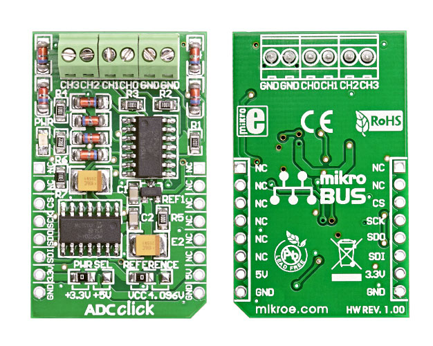
Front and back view of ADC click board designed in mikroBUS form factor. mikroBUS is specially designed pinout standard with SPI, I2C, Analog, UART, Interrupt, PWM, Reset and Power supply pins.

View full image

Library Description

The library covers all the necessary functions that enables the usage of the ADC click board.
It initializes and defines the SPI driver and drivers that offer a choice for reading digital
data from all four channels seperatly or all together.

Key functions:

  • uint16_t adc_getAdcAllChan( uint16_t *valChan0, uint16_t *valChan1, uint16_t *valChan2, uint16_t *valChan3 ); -  Function reads data from all four channels.
  • uint16_t adc_getAdcCh0();-   Function reads data from 0th channel.
  • uint16_t adc_getADC( uint8_t channel ); -   Function reads data from designated channel.

Examples Description

The application is composed of three sections:

  • System Initialization - Initializes SPI module, LOG structure, sets CS pin as output.
  • Application Initialization - Initalizes SPI driver and makes an initial log.
  • Application Task - (code snippet) This is an example that shows the capabilities of the ADC click by taking measurements from all four channel simultaneously.
void applicationTask()
{
    adc_getAdcAllChan( &valChan0, &valChan1, &valChan2, &valChan3 );
    Delay_ms( 100 );
    
    WordToStr( valChan0, txt );
    Ltrim( txt );
    mikrobus_logWrite( " Channel 0 : ", _LOG_TEXT );
    mikrobus_logWrite( txt, _LOG_LINE );

    WordToStr( valChan1, txt );
    Ltrim( txt );
    mikrobus_logWrite( " Channel 1 : ", _LOG_TEXT );
    mikrobus_logWrite( txt, _LOG_LINE );

    WordToStr( valChan2, txt );
    Ltrim( txt );
    mikrobus_logWrite( " Channel 2 : ", _LOG_TEXT );
    mikrobus_logWrite( txt, _LOG_LINE );

    WordToStr( valChan3, txt );
    Ltrim( txt );
    mikrobus_logWrite( " Channel 3 : ", _LOG_TEXT );
    mikrobus_logWrite( txt, _LOG_LINE );

    mikrobus_logWrite( "------------------", _LOG_LINE );
    Delay_ms( 1000 );
}  

Other mikroE Libraries used in the example:

  • SPI
  • UART
  • Conversions

Additional notes and informations

Depending on the development board you are using, you may need USB UART clickUSB UART 2 click or RS232 click to connect to your PC, for development systems with no UART to USB interface available on the board. The terminal available in all MikroElektronika compilers, or any other terminal application of your choice, can be used to read the message

ALSO FROM THIS AUTHOR

UART Demo

0

The application demonstrates UART SDK functionality.

[Learn More]

IR distance Click

0

IR distance Click carries Sharp’s GP2Y0A60SZ0F distance measuring sensor, which comprises of an integrated PSD (position sensitive detector), an infrared LED and a signal processing circuit. The measuring range is between 10 and 150 cm. The Click is designed to run on either 3.3V or 5V power supply. It communicates with the target MCU over RST and AN pin on the mikroBUS™ line.

[Learn More]

Stepper 5 click

5

Stepper 5 click is the complete integrated bipolar step motor driver solution, rich with many features that allow silent operation and optimal working conditions for the connected motor.

[Learn More]