TOP Contributors

  1. MIKROE (2784 codes)
  2. Alcides Ramos (405 codes)
  3. Shawon Shahryiar (307 codes)
  4. jm_palomino (133 codes)
  5. Bugz Bensce (97 codes)
  6. S P (73 codes)
  7. dany (71 codes)
  8. MikroBUS.NET Team (35 codes)
  9. NART SCHINACKOW (34 codes)
  10. Armstrong Subero (27 codes)

Most Downloaded

  1. Timer Calculator (141361 times)
  2. FAT32 Library (74205 times)
  3. Network Ethernet Library (58776 times)
  4. USB Device Library (48854 times)
  5. Network WiFi Library (44564 times)
  6. FT800 Library (44149 times)
  7. GSM click (30883 times)
  8. mikroSDK (29739 times)
  9. PID Library (27372 times)
  10. microSD click (27309 times)
Libstock prefers package manager

Package Manager

We strongly encourage users to use Package manager for sharing their code on Libstock website, because it boosts your efficiency and leaves the end user with no room for error. [more info]

< Back
mikroSDK Library

Heart rate 4 click

Rating:

7

Author: MIKROE

Last Updated: 2019-07-30

Package Version: 1.0.0.1

mikroSDK Library: 1.0.0.0

Category: Biometrics

Downloaded: 7408 times

Not followed.

License: MIT license  

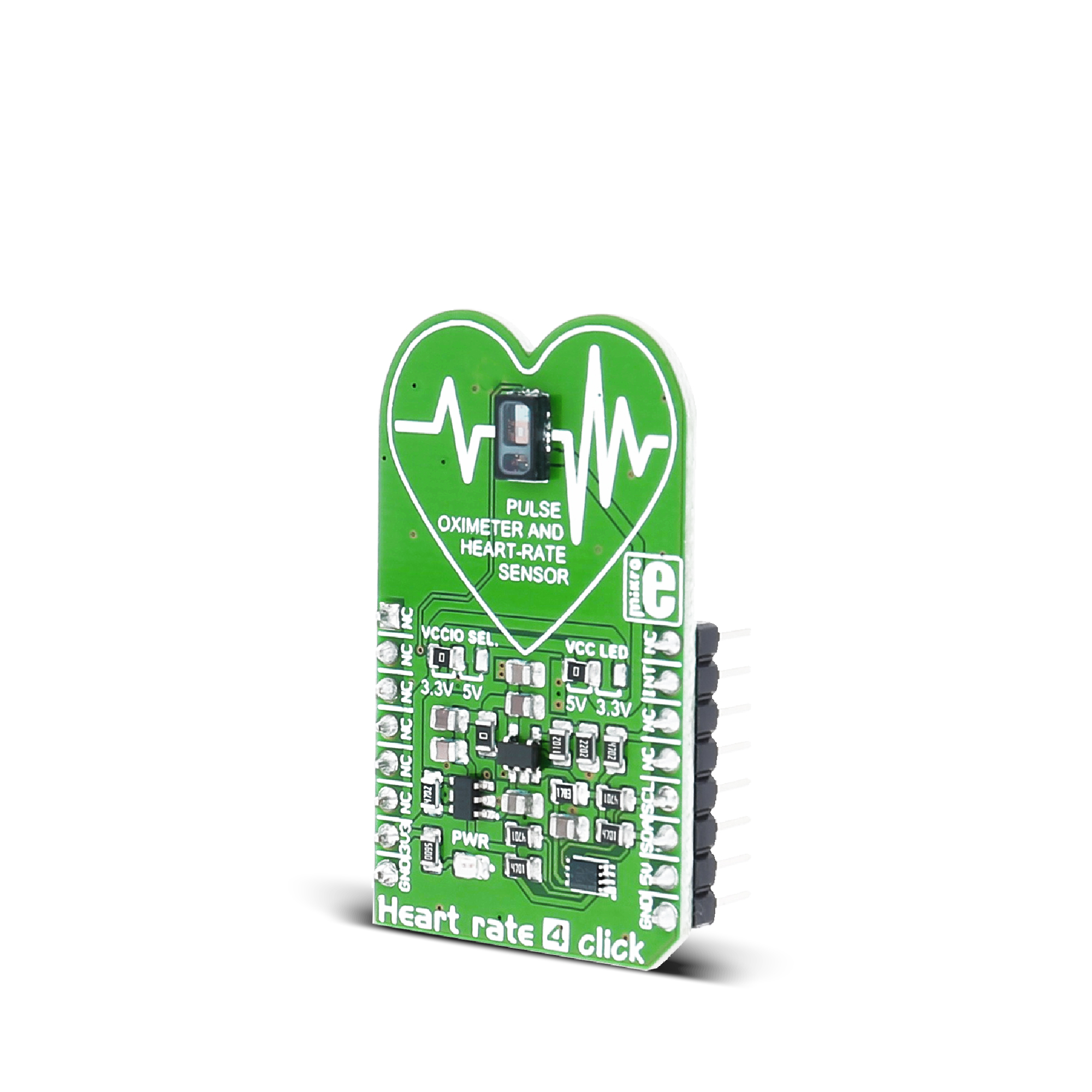
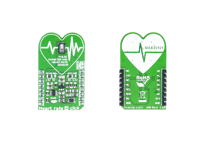
Heart rate 4 click carries the MAX30101 high-sensitivity pulse oximeter and heart-rate sensor from Maxim Integrated. The click is designed to run on either 3.3V or 5V power supply. It communicates with the target MCU over I2C interface, with additional functionality provided by INT pin on the mikroBUS line.

No Abuse Reported

Do you want to subscribe in order to receive notifications regarding "Heart rate 4 click" changes.

Do you want to unsubscribe in order to stop receiving notifications regarding "Heart rate 4 click" changes.

Do you want to report abuse regarding "Heart rate 4 click".

  • mikroSDK Library 2.0.0.0
  • Comments (1)
DOWNLOAD LINK RELATED COMPILER CONTAINS
mikroBasic PRO for ARM
  • lib
  • src
  • exa
  • hlp
  • hex
  • sch
  • pcb
  • doc
mikroBasic PRO for AVR
  • lib
  • src
  • exa
  • hlp
  • hex
  • sch
  • pcb
  • doc
mikroBasic PRO for dsPIC30/33 & PIC24
  • lib
  • src
  • exa
  • hlp
  • hex
  • sch
  • pcb
  • doc
mikroBasic PRO for FT90x
  • lib
  • src
  • exa
  • hlp
  • hex
  • sch
  • pcb
  • doc
mikroBasic PRO for PIC
  • lib
  • src
  • exa
  • hlp
  • hex
  • sch
  • pcb
  • doc
mikroBasic PRO for PIC32
  • lib
  • src
  • exa
  • hlp
  • hex
  • sch
  • pcb
  • doc
mikroC PRO for ARM
  • lib
  • src
  • exa
  • hlp
  • hex
  • sch
  • pcb
  • doc
mikroC PRO for AVR
  • lib
  • src
  • exa
  • hlp
  • hex
  • sch
  • pcb
  • doc
mikroC PRO for dsPIC30/33 & PIC24
  • lib
  • src
  • exa
  • hlp
  • hex
  • sch
  • pcb
  • doc
mikroC PRO for FT90x
  • lib
  • src
  • exa
  • hlp
  • hex
  • sch
  • pcb
  • doc
mikroC PRO for PIC
  • lib
  • src
  • exa
  • hlp
  • hex
  • sch
  • pcb
  • doc
mikroC PRO for PIC32
  • lib
  • src
  • exa
  • hlp
  • hex
  • sch
  • pcb
  • doc
mikroPascal PRO for ARM
  • lib
  • src
  • exa
  • hlp
  • hex
  • sch
  • pcb
  • doc
mikroPascal PRO for AVR
  • lib
  • src
  • exa
  • hlp
  • hex
  • sch
  • pcb
  • doc
mikroPascal PRO for dsPIC30/33 & PIC24
  • lib
  • src
  • exa
  • hlp
  • hex
  • sch
  • pcb
  • doc
mikroPascal PRO for FT90x
  • lib
  • src
  • exa
  • hlp
  • hex
  • sch
  • pcb
  • doc
mikroPascal PRO for PIC
  • lib
  • src
  • exa
  • hlp
  • hex
  • sch
  • pcb
  • doc
mikroPascal PRO for PIC32
  • lib
  • src
  • exa
  • hlp
  • hex
  • sch
  • pcb
  • doc

mikroSDK Library Blog

Heart rate 4 click

Heart rate 4 click

Native view of the Heart rate 4 click board.

View full image

Library Description

The library covers all the necessary functions that enables the usage of the Heart rate 4 Click board. It initializes and defines the I2C bus driver and drivers that offer a choice for writing and reading and setting a new value. Also, user can set, clear or check many different interrupts, as well as read from FIFO register.

Key functions:

  • void heartrate4_setDefaultSettings() - Function is used to apply default settings.
  • uint8_t heartrate4_getInt1() - Function is used to read the main interrupt group.
  • uint32_t heartrate4_getRedVal() - Function is used to read the RED value.

Examples description

The application is composed of three sections :

  • System Initialization - Initializes I2C module, LOG and GPIO structures, sets INT pin as input.
  • Application Initialization - Initalizes I2C driver, applies default settings, and makes an initial log.
  • Application Task - This example demonstrates the use of Heart rate 4 board. It is set in heart rate mode, and reads reflected red values and displays the results on USART terminal.
void applicationTask()
{
    if( heartrate4_getInt1() & 0x40 )
    {
        redSamp = heartrate4_getRedVal();
        if( redSamp > 0 && redSamp < 32000 )
        {
            mikrobus_logWrite( "Place Finger On Sensor", _LOG_LINE );
        }
        else if( redSamp != 0 )
        {
            LongWordToStr( redSamp, logTxt );
            Ltrim( logTxt );
            mikrobus_logWrite( "Heart rate : ", _LOG_TEXT );
            mikrobus_logWrite( logTxt, _LOG_LINE );
        }
        mikrobus_logWrite( "------------------------------", _LOG_LINE );
        Delay_ms( 1000 );
    }
    else
    {
        Delay_ms( 1 );
    }
}

Other mikroE Libraries used in the example:

  • I2C
  • UART
  • Conversions

Additional notes and informations

Depending on the development board you are using, you may need USB UART clickUSB UART 2 click or RS232 click to connect to your PC, for development systems with no UART to USB interface available on the board. The terminal available in all MikroElektronika compilers, or any other terminal application of your choice, can be used to read the message.

Heartrate 4 click

Heartrate 4 click

Front and back view of the Heartrate 4 click board.

View full image

ALSO FROM THIS AUTHOR

Rotary B click

5

Rotary B click carries a 15-pulse incremental rotary encoder with detents, surrounded by a ring of 16 LEDs. It’s a perfect solution for adding a precision input knob to your design. The encoder outputs A and B signals (out of phase to each other); the knob also acts as a push-button which sends an interrupt to the target board MCU.

[Learn More]

RTC 3 Click

0

RTC3 Click carries BQ32000, a real time clock with an integrated trickle charge circuit for automatic switchover to a backup power supply (the circuit maintains the backup charge with an onboard super capacitor).

[Learn More]

MCP251863 Click

0

MCP251863 Click is a compact add-on board representing a complete CAN solution used as a control node in a CAN network. This board features the MCP251863, IC representing a compact solution with a controller and a transceiver in one package, the MCP2518FD and ATA6563 from Microchip. The ATA6563, a low-level physical layer IC (PHY), provides a physical connection with the CAN bus itself, while the CAN controller MCP2518FD represents an interface between the MCU and the PHY. It features three operating modes with dedicated fail-safe features, remote wake-up via CAN, and ideally passive behavior when powered off on the CAN bus. This Click board™ is suitable for developing a wide range of automotive diagnostic applications, even on MCUs that don’t support CAN interface.

[Learn More]