TOP Contributors

  1. MIKROE (2784 codes)
  2. Alcides Ramos (392 codes)
  3. Shawon Shahryiar (307 codes)
  4. jm_palomino (123 codes)
  5. Bugz Bensce (97 codes)
  6. S P (73 codes)
  7. dany (71 codes)
  8. MikroBUS.NET Team (35 codes)
  9. NART SCHINACKOW (34 codes)
  10. Armstrong Subero (27 codes)

Most Downloaded

  1. Timer Calculator (140553 times)
  2. FAT32 Library (73048 times)
  3. Network Ethernet Library (58051 times)
  4. USB Device Library (48223 times)
  5. Network WiFi Library (43833 times)
  6. FT800 Library (43295 times)
  7. GSM click (30359 times)
  8. mikroSDK (28993 times)
  9. PID Library (27119 times)
  10. microSD click (26722 times)
Libstock prefers package manager

Package Manager

We strongly encourage users to use Package manager for sharing their code on Libstock website, because it boosts your efficiency and leaves the end user with no room for error. [more info]

< Back
mikroSDK Library

iqRF 2 click

Rating:

0

Author: MIKROE

Last Updated: 2019-08-05

Package Version: 1.0.0.1

mikroSDK Library: 1.0.0.0

Category: Sub-1 GHz Transceivers

Downloaded: 4466 times

Not followed.

License: MIT license  

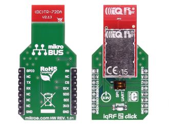
IQRF 2 click carries the DCTR-72DAT RF transceiver, operating in the 868/916 MHz frequency. The click is designed to run on a 3.3V power supply. It communicates with the target microcontroller over SPI or UART interface.

No Abuse Reported

Do you want to subscribe in order to receive notifications regarding "iqRF 2 click" changes.

Do you want to unsubscribe in order to stop receiving notifications regarding "iqRF 2 click" changes.

Do you want to report abuse regarding "iqRF 2 click".
  • mikroSDK Library 2.0.0.0
  • Comments (0)
DOWNLOAD LINK RELATED COMPILER CONTAINS
mikroBasic PRO for ARM
  • lib
  • src
  • exa
  • hlp
  • hex
  • sch
  • pcb
  • doc
mikroBasic PRO for AVR
  • lib
  • src
  • exa
  • hlp
  • hex
  • sch
  • pcb
  • doc
mikroBasic PRO for dsPIC30/33 & PIC24
  • lib
  • src
  • exa
  • hlp
  • hex
  • sch
  • pcb
  • doc
mikroBasic PRO for FT90x
  • lib
  • src
  • exa
  • hlp
  • hex
  • sch
  • pcb
  • doc
mikroBasic PRO for PIC
  • lib
  • src
  • exa
  • hlp
  • hex
  • sch
  • pcb
  • doc
mikroBasic PRO for PIC32
  • lib
  • src
  • exa
  • hlp
  • hex
  • sch
  • pcb
  • doc
mikroC PRO for ARM
  • lib
  • src
  • exa
  • hlp
  • hex
  • sch
  • pcb
  • doc
mikroC PRO for AVR
  • lib
  • src
  • exa
  • hlp
  • hex
  • sch
  • pcb
  • doc
mikroC PRO for dsPIC30/33 & PIC24
  • lib
  • src
  • exa
  • hlp
  • hex
  • sch
  • pcb
  • doc
mikroC PRO for FT90x
  • lib
  • src
  • exa
  • hlp
  • hex
  • sch
  • pcb
  • doc
mikroC PRO for PIC
  • lib
  • src
  • exa
  • hlp
  • hex
  • sch
  • pcb
  • doc
mikroC PRO for PIC32
  • lib
  • src
  • exa
  • hlp
  • hex
  • sch
  • pcb
  • doc
mikroPascal PRO for ARM
  • lib
  • src
  • exa
  • hlp
  • hex
  • sch
  • pcb
  • doc
mikroPascal PRO for AVR
  • lib
  • src
  • exa
  • hlp
  • hex
  • sch
  • pcb
  • doc
mikroPascal PRO for dsPIC30/33 & PIC24
  • lib
  • src
  • exa
  • hlp
  • hex
  • sch
  • pcb
  • doc
mikroPascal PRO for FT90x
  • lib
  • src
  • exa
  • hlp
  • hex
  • sch
  • pcb
  • doc
mikroPascal PRO for PIC
  • lib
  • src
  • exa
  • hlp
  • hex
  • sch
  • pcb
  • doc
mikroPascal PRO for PIC32
  • lib
  • src
  • exa
  • hlp
  • hex
  • sch
  • pcb
  • doc

mikroSDK Library Blog

IQRF 2 click

IQRF 2 click

Front and back view of the IQRF 2 click board.

View full image

Library Description

The library covers all the necessary functions to control iqRF 2 Click board.

Key functions:

  • void iqrf2_writeByte(uint8_t input) - Write Single Byte.
  • uint8_t iqrf2_readByte() - Read Single Byte.
  • uint8_t iqrf2_byteReady() - Check for new byte received.

Examples description

The application is composed of the three sections :

  • System Initialization - Initializes UART and LOG structures and start to write log.
  • Application Initialization - Initialization driver enables - UART, also write log.
  • Application Task - This is an example which demonstrates the use of iqRF 2 click board. Checks if new data byte has received in RX buffer ( ready for reading ), and if ready than reads one byte from RX buffer. In the second case, the application task writes message data via UART. Results are being sent to the Usart Terminal where you can track their changes
void applicationTask()
{
    char tmp;
    uint8_t rdyFlag;

// RECEIVER - UART polling

    rdyFlag = iqrf2_byteReady();

    if (1 == rdyFlag)
    {
        tmp = iqrf2_readByte();
        mikrobus_logWrite( &tmp, _LOG_BYTE );
    }

// TRANSMITER - TX each 2 sec
/*
    for (tmp = 0; tmp < 9; tmp++)
    {
        iqrf2_writeByte( MESSAGE_DATA[tmp] );
        Delay_ms( 100 );   
    }

    Delay_ms( 2000 );
*/
}

Other mikroE Libraries used in the example:

  • UART

Additional notes and informations

Depending on the development board you are using, you may need USB UART clickUSB UART 2 click or RS232 click to connect to your PC, for development systems with no UART to USB interface available on the board. The terminal available in all MikroElektronika compilers, or any other terminal application of your choice, can be used to read the message.

ALSO FROM THIS AUTHOR

I2C Extend 2 Click

0

I2C Extend 2 Click is a compact add-on board suitable for I2C communication bus extension. This board features the PCA9615, a 2-channel multipoint differential I2C bus buffer with hot-swap logic from NXP Semiconductors. The PCA9615 converts the two default I2C signals into four differential signals, two for SCL and two for SDA.

[Learn More]

MAC Address Click

0

MAC Address Click provides a unique node address for your application. It also has 1Kbit of writable EEPROM memory.

[Learn More]

EERAM 3v3 Click

0

EERAM 3.3V Click is a static RAM (SRAM) memory Click board™ with the unique feature - it has a backup non-volatile memory array, used to store the data from the SRAM array. Since the SRAM is not able to maintain its content after the power loss, the non-volatile EEPROM backup can be a very handy addition that can be used to preserve the data, even after the power loss event. This is a very useful feature when working with critical or sensitive applications. The memory backup procedure can be executed both automatically and manually. When it is set to work in the manual mode, the onboard capacitor will act as a power source with enough power to complete the backup cycle. The power-on backup restore mode is also available, taking only about 25ms to complete.

[Learn More]