TOP Contributors

  1. MIKROE (2784 codes)
  2. Alcides Ramos (387 codes)
  3. Shawon Shahryiar (307 codes)
  4. jm_palomino (120 codes)
  5. Bugz Bensce (97 codes)
  6. S P (73 codes)
  7. dany (71 codes)
  8. MikroBUS.NET Team (35 codes)
  9. NART SCHINACKOW (34 codes)
  10. Armstrong Subero (27 codes)

Most Downloaded

  1. Timer Calculator (140167 times)
  2. FAT32 Library (72621 times)
  3. Network Ethernet Library (57641 times)
  4. USB Device Library (47954 times)
  5. Network WiFi Library (43553 times)
  6. FT800 Library (42942 times)
  7. GSM click (30140 times)
  8. mikroSDK (28669 times)
  9. PID Library (27055 times)
  10. microSD click (26552 times)
Libstock prefers package manager

Package Manager

We strongly encourage users to use Package manager for sharing their code on Libstock website, because it boosts your efficiency and leaves the end user with no room for error. [more info]

< Back
mikroSDK Library

DC Motor 5 click

Rating:

0

Author: MIKROE

Last Updated: 2019-03-08

Package Version: 1.0.0.1

mikroSDK Library: 1.0.0.0

Category: Brushed

Downloaded: 4750 times

Not followed.

License: MIT license  

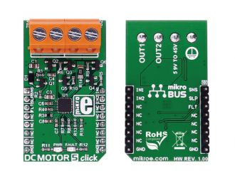
DC MOTOR 5 click carries the DRV8701 brushed DC motor gate driver from Texas Instruments. The click is designed to run on an external power supply. It communicates with the target MCU over the following pins on the mikroBUSâ„¢ line: AN, RST, CS, PWM, and INT.

No Abuse Reported

Do you want to subscribe in order to receive notifications regarding "DC Motor 5 click" changes.

Do you want to unsubscribe in order to stop receiving notifications regarding "DC Motor 5 click" changes.

Do you want to report abuse regarding "DC Motor 5 click".
  • mikroSDK Library 2.0.0.0
  • Comments (0)
DOWNLOAD LINK RELATED COMPILER CONTAINS
mikroBasic PRO for ARM
  • lib
  • src
  • exa
  • hlp
  • hex
  • sch
  • pcb
  • doc
mikroBasic PRO for AVR
  • lib
  • src
  • exa
  • hlp
  • hex
  • sch
  • pcb
  • doc
mikroBasic PRO for dsPIC30/33 & PIC24
  • lib
  • src
  • exa
  • hlp
  • hex
  • sch
  • pcb
  • doc
mikroBasic PRO for FT90x
  • lib
  • src
  • exa
  • hlp
  • hex
  • sch
  • pcb
  • doc
mikroBasic PRO for PIC
  • lib
  • src
  • exa
  • hlp
  • hex
  • sch
  • pcb
  • doc
mikroBasic PRO for PIC32
  • lib
  • src
  • exa
  • hlp
  • hex
  • sch
  • pcb
  • doc
mikroC PRO for ARM
  • lib
  • src
  • exa
  • hlp
  • hex
  • sch
  • pcb
  • doc
mikroC PRO for AVR
  • lib
  • src
  • exa
  • hlp
  • hex
  • sch
  • pcb
  • doc
mikroC PRO for dsPIC30/33 & PIC24
  • lib
  • src
  • exa
  • hlp
  • hex
  • sch
  • pcb
  • doc
mikroC PRO for FT90x
  • lib
  • src
  • exa
  • hlp
  • hex
  • sch
  • pcb
  • doc
mikroC PRO for PIC
  • lib
  • src
  • exa
  • hlp
  • hex
  • sch
  • pcb
  • doc
mikroC PRO for PIC32
  • lib
  • src
  • exa
  • hlp
  • hex
  • sch
  • pcb
  • doc
mikroPascal PRO for ARM
  • lib
  • src
  • exa
  • hlp
  • hex
  • sch
  • pcb
  • doc
mikroPascal PRO for AVR
  • lib
  • src
  • exa
  • hlp
  • hex
  • sch
  • pcb
  • doc
mikroPascal PRO for dsPIC30/33 & PIC24
  • lib
  • src
  • exa
  • hlp
  • hex
  • sch
  • pcb
  • doc
mikroPascal PRO for FT90x
  • lib
  • src
  • exa
  • hlp
  • hex
  • sch
  • pcb
  • doc
mikroPascal PRO for PIC
  • lib
  • src
  • exa
  • hlp
  • hex
  • sch
  • pcb
  • doc
mikroPascal PRO for PIC32
  • lib
  • src
  • exa
  • hlp
  • hex
  • sch
  • pcb
  • doc

mikroSDK Library Blog

DC Motor 5 click

DC Motor 5 click

Front and back view of the DC Motor 5 click board.

View full image

Library Description

The library covers all the necessary functions to control DC Motor 5 Click board.
DC Motor 5 Click communicates with the target board via the PWM module.
This library contains drivers to enable or disable the engine, 
for rotation in the clockwise or counterclockwise direction, for the brake and stop the motor and
for PWM function: initialization, for sets duty ratio, starts and stops PWM module.

Key functions:

  • void dcmotor5_enable() - Enable the motor function.
  • void dcmotor5_counterClockwise()- Set the direction of rotation in the counter clockwise direction function.
  • void dcmotor5_clockwise() - Set the direction of rotation in the clockwise direction function.

Examples description

The application is composed of three sections:

  • System Initialization - Initializes GPIO and LOG structures, sets AN and CS pins as input, sets RST, PWM, and INT pins as output.
  • Application Initialization -  Initialization driver enables - GPIO, PWM initialization set PWM duty cycle and PWM frequency, start PWM, enable the engine, and start to write log.
  • Application Task - (code snippet) This is an example which demonstrates the use of DC Motor 5 Click board. DC Motor 5 Click communicates with register via PWM interface.
    Its shows moving in the clockwise direction of rotation from slow to fast speed and moving in the counterclockwise direction of rotation from fast to slow speed.
    Results are being sent to the Usart Terminal where you can track their changes.
void applicationTask() 
{
    mikrobus_logWrite( "   Brake the engine  ", _LOG_LINE );
    dcmotor5_shortBrake();
    Delay_1sec();
    
    mikrobus_logWrite( "---------------------", _LOG_LINE );
    mikrobus_logWrite( "      Clockwise      ", _LOG_LINE );
    dcmotor5_clockwise();
    Delay_1sec();
 
    for ( dutyCycle = 500; dutyCycle < 3000; dutyCycle += 250 )
    {
        dcmotor5_pwmSetDuty( dutyCycle );
        mikrobus_logWrite( " >", _LOG_TEXT );
        Delay_1sec();
    }
 
    mikrobus_logWrite( "", _LOG_LINE );
    mikrobus_logWrite( "---------------------", _LOG_LINE );
    mikrobus_logWrite( "   Brake the engine  ", _LOG_LINE );
    dcmotor5_shortBrake();
    Delay_1sec();

    mikrobus_logWrite( "---------------------", _LOG_LINE );  
    mikrobus_logWrite( "  Counter Clockwise  ", _LOG_LINE );
    dcmotor5_counterClockwise();
    Delay_1sec();
 
    for ( dutyCycle = 3000; dutyCycle > 500; dutyCycle -= 250 )
    {
        dcmotor5_pwmSetDuty( dutyCycle );
        mikrobus_logWrite( " <", _LOG_TEXT );
        Delay_1sec();
    }
  
    mikrobus_logWrite( "", _LOG_LINE );
    mikrobus_logWrite( "---------------------", _LOG_LINE );
    Delay_1sec();
}  

Additional Functions :

  • uint32_t dcmotor5_pwmInit( uint16_t freq ) - Initializes the Timer module in PWM mode.
  • void dcmotor5_pwmSetDuty( uint16_t duty ) - The function changes PWM duty ratio.
  • void dcmotor5_pwmStart() Starts appropriate PWM module.
  • void dcmotor5_pwmStop() - Stops appropriate PWM module.

Other mikroE Libraries used in the example:

  • PWM
  • UART

Additional notes and informations

Depending on the development board you are using, you may need USB UART clickUSB UART 2 click or RS232 click to connect to your PC, for development systems with no UART to USB interface available on the board. The terminal available in all MikroElektronika compilers, or any other terminal application of your choice, can be used to read the message

ALSO FROM THIS AUTHOR

Buck 5 click

5

Buck 5 click is a high-efficiency buck (step-down) DC/DC converter, which can provide digitally adjusted step-down voltage on its output while delivering a considerable amount of current.

[Learn More]

4G LTE 2 Voice Click

0

4G LTE 2 Click is a compact add-on board representing a secure-cloud multi-band solution offering universal connectivity and reliable performance. This board features the LARA-R6001, the world’s smallest LTE Cat 1 module with global coverage and a built-in MQTT client from u-blox, representing a data and voice solution. Equipped with familiar AT commands set over the UART interface, USB interface, and Network and Status indicators, the LARA-R6001 also has a comprehensive certification scheme and multi-band/multi-mode capabilities providing excellent flexibility alongside the support of voice/audio application.

[Learn More]

HW Monitor 2 Click

0

HW Monitor 2 Click is a compact add-on board used to monitor and regulate the performance of various hardware components within an embedded system. This board features the AMC80, an I2C-configurable system hardware monitor from Texas Instruments that contains a 10-bit ADC capable of measuring seven positive voltages and local temperature. The AMC80 also has two programmable fan speed monitoring inputs besides other hardware monitoring functions like chassis intrusion detection, additional external interrupt input, and master reset for external purposes, as well as a programmable upper over-limit and lower under-limit alarms that activate when the programmed limits are exceeded.

[Learn More]