TOP Contributors

  1. MIKROE (2784 codes)
  2. Alcides Ramos (405 codes)
  3. Shawon Shahryiar (307 codes)
  4. jm_palomino (133 codes)
  5. Bugz Bensce (97 codes)
  6. S P (73 codes)
  7. dany (71 codes)
  8. MikroBUS.NET Team (35 codes)
  9. NART SCHINACKOW (34 codes)
  10. Armstrong Subero (27 codes)

Most Downloaded

  1. Timer Calculator (141825 times)
  2. FAT32 Library (74956 times)
  3. Network Ethernet Library (59316 times)
  4. USB Device Library (49308 times)
  5. Network WiFi Library (45107 times)
  6. FT800 Library (44675 times)
  7. GSM click (31287 times)
  8. mikroSDK (30214 times)
  9. microSD click (27664 times)
  10. PID Library (27563 times)
Libstock prefers package manager

Package Manager

We strongly encourage users to use Package manager for sharing their code on Libstock website, because it boosts your efficiency and leaves the end user with no room for error. [more info]

< Back
mikroSDK Library

Boost 4 click

Rating:

2

Author: MIKROE

Last Updated: 2019-01-10

Package Version: 1.0.0.1

mikroSDK Library: 1.0.0.0

Category: Boost

Downloaded: 5925 times

Not followed.

License: MIT license  

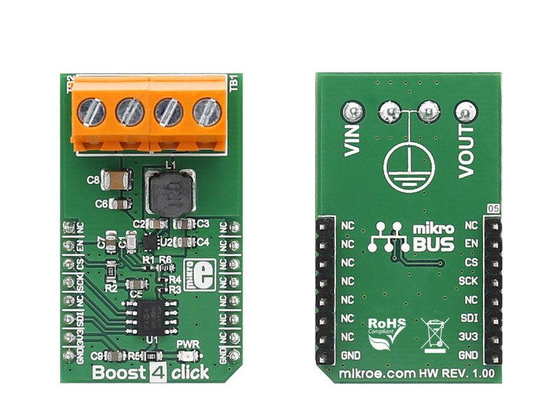
Boost 4 click carries the TPS61230A, a high efficiency fully integrated synchronous boost converter from Texas Instruments. The click is designed to run on a 3.3V power supply. It communicates with the target microcontroller over SPI interface.

No Abuse Reported

Do you want to subscribe in order to receive notifications regarding "Boost 4 click" changes.

Do you want to unsubscribe in order to stop receiving notifications regarding "Boost 4 click" changes.

Do you want to report abuse regarding "Boost 4 click".

  • mikroSDK Library 2.0.0.0
  • Comments (0)
DOWNLOAD LINK RELATED COMPILER CONTAINS
mikroBasic PRO for ARM
  • lib
  • src
  • exa
  • hlp
  • hex
  • sch
  • pcb
  • doc
mikroBasic PRO for AVR
  • lib
  • src
  • exa
  • hlp
  • hex
  • sch
  • pcb
  • doc
mikroBasic PRO for dsPIC30/33 & PIC24
  • lib
  • src
  • exa
  • hlp
  • hex
  • sch
  • pcb
  • doc
mikroBasic PRO for FT90x
  • lib
  • src
  • exa
  • hlp
  • hex
  • sch
  • pcb
  • doc
mikroBasic PRO for PIC
  • lib
  • src
  • exa
  • hlp
  • hex
  • sch
  • pcb
  • doc
mikroBasic PRO for PIC32
  • lib
  • src
  • exa
  • hlp
  • hex
  • sch
  • pcb
  • doc
mikroC PRO for ARM
  • lib
  • src
  • exa
  • hlp
  • hex
  • sch
  • pcb
  • doc
mikroC PRO for AVR
  • lib
  • src
  • exa
  • hlp
  • hex
  • sch
  • pcb
  • doc
mikroC PRO for dsPIC30/33 & PIC24
  • lib
  • src
  • exa
  • hlp
  • hex
  • sch
  • pcb
  • doc
mikroC PRO for FT90x
  • lib
  • src
  • exa
  • hlp
  • hex
  • sch
  • pcb
  • doc
mikroC PRO for PIC
  • lib
  • src
  • exa
  • hlp
  • hex
  • sch
  • pcb
  • doc
mikroC PRO for PIC32
  • lib
  • src
  • exa
  • hlp
  • hex
  • sch
  • pcb
  • doc
mikroPascal PRO for ARM
  • lib
  • src
  • exa
  • hlp
  • hex
  • sch
  • pcb
  • doc
mikroPascal PRO for AVR
  • lib
  • src
  • exa
  • hlp
  • hex
  • sch
  • pcb
  • doc
mikroPascal PRO for dsPIC30/33 & PIC24
  • lib
  • src
  • exa
  • hlp
  • hex
  • sch
  • pcb
  • doc
mikroPascal PRO for FT90x
  • lib
  • src
  • exa
  • hlp
  • hex
  • sch
  • pcb
  • doc
mikroPascal PRO for PIC
  • lib
  • src
  • exa
  • hlp
  • hex
  • sch
  • pcb
  • doc
mikroPascal PRO for PIC32
  • lib
  • src
  • exa
  • hlp
  • hex
  • sch
  • pcb
  • doc

mikroSDK Library Blog

Boost 4 click

Boost 4 click

Front and back view of the Boost 4 click board.

View full image

Library Description

The library covers all the necessary functions to control Boost 4 Click board.
Boost 4 click communicates with the target board via SPI protocol. 
This library contains drivers for enable the device regulator, forces the device into shutdown mode,
for sets output voltage and for sets min and max output voltage.

Key functions:

  • void boost4_enable() - Enable the device regulator function.
  • void boost4_setOutVoltage( uint16_t value ) - Set output voltage function.
  • void boost4_setOutVoltageMax() - Set the maximum output voltage function.

Examples description

The application is composed of the three sections :

  • System Initialization - Initializes GPIO, SPI and LOG structures,
         sets CS and RST pins as output.
  • Application Initialization - Initialization driver enable's - SPI,
         enable the device regulator and start write log.
  • Application Task - (code snippet) This is a example which demonstrates the use of Boost 4 Click board. Boost 4 Click communicates with register via SPI by write value to the TPS61230A chip. This example shows how to set the desired output voltage, by cycling through a couple of predefined voltage values.
    All data logs write on usb uart for aproximetly every 5 sec.
void applicationTask()
{
    mikrobus_logWrite( " Set the max Vout ~ 5.25 V ", _LOG_LINE );
 
    boost4_setOutVoltageMax();
    Delay_ms( 5000 );

    mikrobus_logWrite( "-----------------------------", _LOG_LINE );
    mikrobus_logWrite( " Set the min Vout ~ 3.05 V ", _LOG_LINE );

    boost4_setOutVoltageMin();
    Delay_ms( 5000 );

    mikrobus_logWrite( "-----------------------------", _LOG_LINE );

}

Other mikroE Libraries used in the example:

  • SPI
  • UART

Additional notes and information

Depending on the development board you are using, you may need USB UART clickUSB UART 2 click or RS232 click to connect to your PC, for development systems with no UART to USB interface available on the board. The terminal available in all MikroElektronika compilers, or any other terminal application of your choice, can be used to read the message.

ALSO FROM THIS AUTHOR

Matrix G Click

0

Matrix G Click is a mikroBUS add-on board with two green 5x7 matrices driven by two MAX7219 8-bit LED Display Drivers. The active area of each matrix is 7.62mm high and 5.08 mm wide. 7x5 is a standard resolution for displaying ASCII characters, so the Click is essentially a dual-character display capable of showing letters in more readable typefaces compared to a 14-segment display. The Click communicates with the target MCU through the mikroBUS SPI interface with two separate Chip Select lines for each matrix (CSL for the left, CSR for the right). This board is designed to use a 5V power supply.

[Learn More]

LED Blinking Demo

0

The application demonstrates GPIO SDK functionality.

[Learn More]

IrThermo 2 Click

0

IrThermo 2 Click is a non-contact temperature measurement solution. The Click board carries the TMP007 infrared thermopile sensor with an integrated math engine.

[Learn More]