TOP Contributors

  1. MIKROE (2784 codes)
  2. Alcides Ramos (385 codes)
  3. Shawon Shahryiar (307 codes)
  4. jm_palomino (118 codes)
  5. Bugz Bensce (97 codes)
  6. S P (73 codes)
  7. dany (71 codes)
  8. MikroBUS.NET Team (35 codes)
  9. NART SCHINACKOW (34 codes)
  10. Armstrong Subero (27 codes)

Most Downloaded

  1. Timer Calculator (139847 times)
  2. FAT32 Library (72210 times)
  3. Network Ethernet Library (57392 times)
  4. USB Device Library (47740 times)
  5. Network WiFi Library (43364 times)
  6. FT800 Library (42700 times)
  7. GSM click (29980 times)
  8. mikroSDK (28442 times)
  9. PID Library (26989 times)
  10. microSD click (26398 times)
Libstock prefers package manager

Package Manager

We strongly encourage users to use Package manager for sharing their code on Libstock website, because it boosts your efficiency and leaves the end user with no room for error. [more info]

< Back
mikroSDK Library

FRAM 2 click

Rating:

0

Author: MIKROE

Last Updated: 2018-03-13

Package Version: 1.0.0.1

mikroSDK Library: 1.0.0.0

Category: FRAM

Downloaded: 5921 times

Not followed.

License: MIT license  

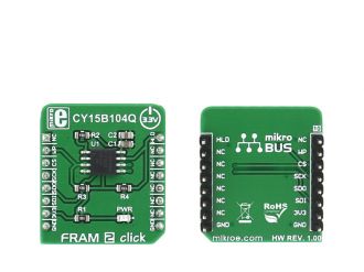
FRAM 2 click carries the CY15B104Q 4-Mbit (512K x 8 serial F-RAM. A ferroelectric random-access memory or F-RAM is non-volatile and performs reads and writes similar to a RAM. The memory is accessed using an industry-standard serial peripheral interface (SPI) bus.

No Abuse Reported

Do you want to subscribe in order to receive notifications regarding "FRAM 2 click" changes.

Do you want to unsubscribe in order to stop receiving notifications regarding "FRAM 2 click" changes.

Do you want to report abuse regarding "FRAM 2 click".
  • mikroSDK Library 2.0.0.0
  • Comments (0)
DOWNLOAD LINK RELATED COMPILER CONTAINS
mikroBasic PRO for ARM
  • lib
  • src
  • exa
  • hlp
  • hex
  • sch
  • pcb
  • doc
mikroBasic PRO for AVR
  • lib
  • src
  • exa
  • hlp
  • hex
  • sch
  • pcb
  • doc
mikroBasic PRO for dsPIC30/33 & PIC24
  • lib
  • src
  • exa
  • hlp
  • hex
  • sch
  • pcb
  • doc
mikroBasic PRO for FT90x
  • lib
  • src
  • exa
  • hlp
  • hex
  • sch
  • pcb
  • doc
mikroBasic PRO for PIC
  • lib
  • src
  • exa
  • hlp
  • hex
  • sch
  • pcb
  • doc
mikroBasic PRO for PIC32
  • lib
  • src
  • exa
  • hlp
  • hex
  • sch
  • pcb
  • doc
mikroC PRO for ARM
  • lib
  • src
  • exa
  • hlp
  • hex
  • sch
  • pcb
  • doc
mikroC PRO for AVR
  • lib
  • src
  • exa
  • hlp
  • hex
  • sch
  • pcb
  • doc
mikroC PRO for dsPIC30/33 & PIC24
  • lib
  • src
  • exa
  • hlp
  • hex
  • sch
  • pcb
  • doc
mikroC PRO for FT90x
  • lib
  • src
  • exa
  • hlp
  • hex
  • sch
  • pcb
  • doc
mikroC PRO for PIC
  • lib
  • src
  • exa
  • hlp
  • hex
  • sch
  • pcb
  • doc
mikroC PRO for PIC32
  • lib
  • src
  • exa
  • hlp
  • hex
  • sch
  • pcb
  • doc
mikroPascal PRO for ARM
  • lib
  • src
  • exa
  • hlp
  • hex
  • sch
  • pcb
  • doc
mikroPascal PRO for AVR
  • lib
  • src
  • exa
  • hlp
  • hex
  • sch
  • pcb
  • doc
mikroPascal PRO for dsPIC30/33 & PIC24
  • lib
  • src
  • exa
  • hlp
  • hex
  • sch
  • pcb
  • doc
mikroPascal PRO for FT90x
  • lib
  • src
  • exa
  • hlp
  • hex
  • sch
  • pcb
  • doc
mikroPascal PRO for PIC
  • lib
  • src
  • exa
  • hlp
  • hex
  • sch
  • pcb
  • doc
mikroPascal PRO for PIC32
  • lib
  • src
  • exa
  • hlp
  • hex
  • sch
  • pcb
  • doc

mikroSDK Library Blog

FRAM 2 click

FRAM 2 click

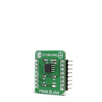
Native view of the FRAM 2 click board.

View full image
FRAM 2 click

FRAM 2 click

Front and back view of the FRAM 2 click board.

View full image

Library Description

Key functions:

  • void fram_write(uint32_t address, uint8_t *buffer, uint16_t counter) - The function writes to sequential memory locations from the buffer.
  • void fram_read(uint32_t address, uint8_t *buffer, uint16_t count) - The function reads sequential memory locations to the buffer.
  • void fram_writeEnable() - The function enables data writing in the FRAM memory space.

Examples Description

The application is composed of three sections:

  • System Initialization - GPIO and SPI module Initialization.
  • Application Initialization -  Fram 2 Driver Initialization, initialization of click by setting mikorBUS pins to an appropriate logic level, performing erase all and write enable functions.
  • Application Task - Writing data to click memory and displaying the read data via UART.
void applicationTask()
{
 mikrobus_logWrite("Writing MikroE to Fram memory, from address 0x015015:",
_LOG_LINE);
 fram2_write (0x015015, &wrData[0], 9);

 mikrobus_logWrite("Reading 9 bytes of Fram memory, from address 0x015015:",
_LOG_LINE);
 fram2_read(0x015015,&rdData[0],9);

 mikrobus_logWrite("Data read: ",_LOG_TEXT);
 mikrobus_logWrite(rdData,_LOG_LINE);

 Delay_ms(1000);
}

Other mikroE Libraries used in the example:

  • UART
  • SPI

Additional notes and information

Depending on the development board you are using, you may need USB UART click,  USB UART 2 click or RS232 click to connect to your PC, for development systems with no UART to USB interface available on the board. The terminal available in all MikroElektronika compilers, or any other terminal application of your choice, can be used to read the message.


ALSO FROM THIS AUTHOR

ATA663254 click

5

ATA663254 click is a fully integrated LIN transceiver device with an integrated 5V LDO voltage regulator.

[Learn More]

Grid-EYE 2 Click

0

Grid-EYE 2 Click is a compact add-on board designed for thermal imaging and motion detection applications. This board features the AMG883543, an infrared array sensor from Panasonic with a 90° viewing angle and an 8x8 pixel matrix that measures temperatures from 0°C to 80°C with a resolution of 0.25°C. The sensor can detect objects up to 5 meters away and outputs temperature data via a digital interface. The board also supports the Click Snap feature, allowing the main sensor area to be detached for flexible positioning.

[Learn More]

RTC 2 click

0

Example for RTC2 click board in mikroBUS form factor. It is a simple demonstration how to read/write date and time from DS1307 RTC (real-time clock). Date and time are read from the RTC every 10 milliseconds and printed on LCD. Communication with the board is done via I2C interface.

[Learn More]