TOP Contributors

  1. MIKROE (2784 codes)
  2. Alcides Ramos (405 codes)
  3. Shawon Shahryiar (307 codes)
  4. jm_palomino (133 codes)
  5. Bugz Bensce (97 codes)
  6. S P (73 codes)
  7. dany (71 codes)
  8. MikroBUS.NET Team (35 codes)
  9. NART SCHINACKOW (34 codes)
  10. Armstrong Subero (27 codes)

Most Downloaded

  1. Timer Calculator (141478 times)
  2. FAT32 Library (74335 times)
  3. Network Ethernet Library (58867 times)
  4. USB Device Library (48921 times)
  5. Network WiFi Library (44697 times)
  6. FT800 Library (44227 times)
  7. GSM click (30937 times)
  8. mikroSDK (29817 times)
  9. PID Library (27423 times)
  10. microSD click (27375 times)
Libstock prefers package manager

Package Manager

We strongly encourage users to use Package manager for sharing their code on Libstock website, because it boosts your efficiency and leaves the end user with no room for error. [more info]

< Back
mikroSDK Library

Boost click

Rating:

2

Author: MIKROE

Last Updated: 2019-01-09

Package Version: 1.0.0.1

mikroSDK Library: 1.0.0.0

Category: Boost

Downloaded: 6162 times

Not followed.

License: MIT license  

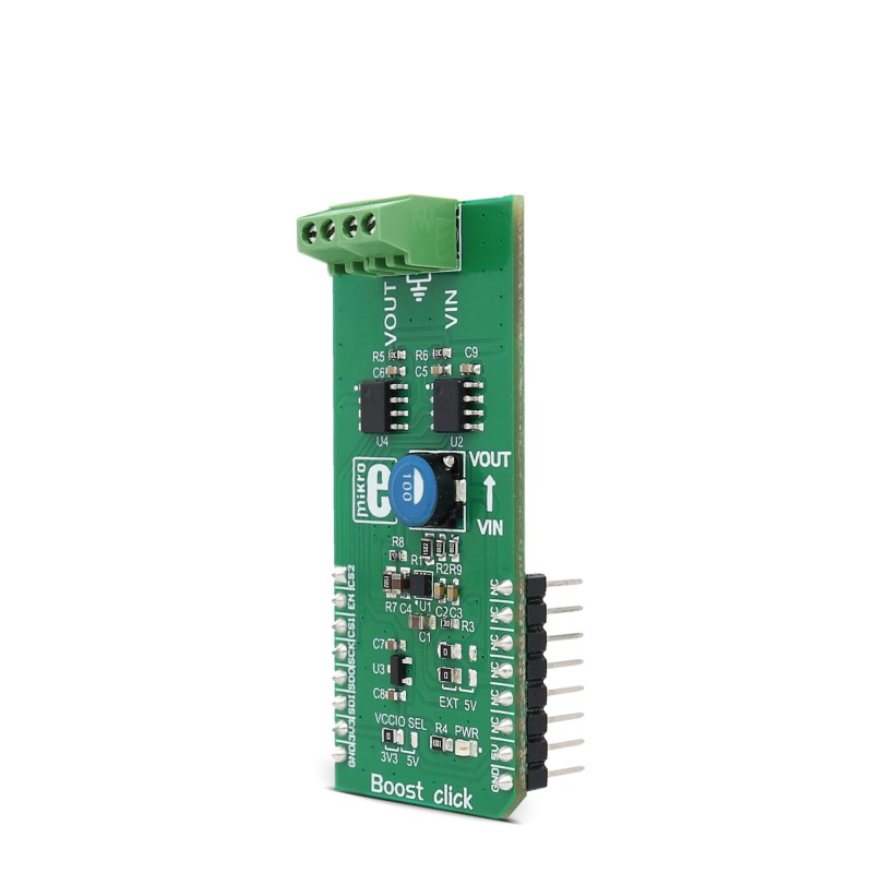
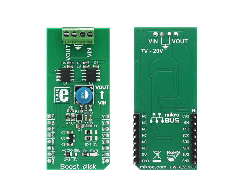
Boost click carries Microchip’s MIC2606, a 2MHz, PWM DC/DC boost switching regulator available in a 2mm x 2mm MLF package. The input voltage can be set to 5V from mikroBUS or in range 7-20V from an external DC source connected to VIN screw terminal. The output voltage can be set up to 38V.

No Abuse Reported

Do you want to subscribe in order to receive notifications regarding "Boost click" changes.

Do you want to unsubscribe in order to stop receiving notifications regarding "Boost click" changes.

Do you want to report abuse regarding "Boost click".

  • mikroSDK Library 2.0.0.0
  • Comments (0)
DOWNLOAD LINK RELATED COMPILER CONTAINS
mikroBasic PRO for ARM
  • lib
  • src
  • exa
  • hlp
  • hex
  • sch
  • pcb
  • doc
mikroBasic PRO for AVR
  • lib
  • src
  • exa
  • hlp
  • hex
  • sch
  • pcb
  • doc
mikroBasic PRO for dsPIC30/33 & PIC24
  • lib
  • src
  • exa
  • hlp
  • hex
  • sch
  • pcb
  • doc
mikroBasic PRO for FT90x
  • lib
  • src
  • exa
  • hlp
  • hex
  • sch
  • pcb
  • doc
mikroBasic PRO for PIC
  • lib
  • src
  • exa
  • hlp
  • hex
  • sch
  • pcb
  • doc
mikroBasic PRO for PIC32
  • lib
  • src
  • exa
  • hlp
  • hex
  • sch
  • pcb
  • doc
mikroC PRO for ARM
  • lib
  • src
  • exa
  • hlp
  • hex
  • sch
  • pcb
  • doc
mikroC PRO for AVR
  • lib
  • src
  • exa
  • hlp
  • hex
  • sch
  • pcb
  • doc
mikroC PRO for dsPIC30/33 & PIC24
  • lib
  • src
  • exa
  • hlp
  • hex
  • sch
  • pcb
  • doc
mikroC PRO for FT90x
  • lib
  • src
  • exa
  • hlp
  • hex
  • sch
  • pcb
  • doc
mikroC PRO for PIC
  • lib
  • src
  • exa
  • hlp
  • hex
  • sch
  • pcb
  • doc
mikroC PRO for PIC32
  • lib
  • src
  • exa
  • hlp
  • hex
  • sch
  • pcb
  • doc
mikroPascal PRO for ARM
  • lib
  • src
  • exa
  • hlp
  • hex
  • sch
  • pcb
  • doc
mikroPascal PRO for AVR
  • lib
  • src
  • exa
  • hlp
  • hex
  • sch
  • pcb
  • doc
mikroPascal PRO for dsPIC30/33 & PIC24
  • lib
  • src
  • exa
  • hlp
  • hex
  • sch
  • pcb
  • doc
mikroPascal PRO for FT90x
  • lib
  • src
  • exa
  • hlp
  • hex
  • sch
  • pcb
  • doc
mikroPascal PRO for PIC
  • lib
  • src
  • exa
  • hlp
  • hex
  • sch
  • pcb
  • doc
mikroPascal PRO for PIC32
  • lib
  • src
  • exa
  • hlp
  • hex
  • sch
  • pcb
  • doc

mikroSDK Library Blog

Boost click

Boost click

Native view of the Boost click board.

View full image
Front/Back view

Front/Back view

Front and back view of Boost Click.

View full image

Library Description

The library covers all the necessary functions to control Boost Click board.
Boost click communicates with the target board via SPI protocol. 
This library contains drivers for writing DAC value to the MCP4921 chip and reading ADC value from MCP3551 chip,
set configuration, function for setting desired voltage on output  and function to  getting output voltage.

Key functions:

  • void boost_setConfiguration( uint8_t pwrSrc ) - Set configuration function.
  • float boost_getVoltage()- Get output voltage function.
  • void boost_setVoltage( uint16_t value ) - Set desired voltage on output function.

Examples description

The application is composed of three sections :

- System Initialization - Initializes GPIO, SPI and LOG structures,
     sets AN, CS and RST pins as output.
- Application Initialization - Initialization driver enable's - SPI,
     set configuration and start write log.
- Application Task - (code snippet) This is a example which demonstrates the use of Boost Click board.
     Boost Click communicates with register via SPI by read from MCP3551 chip and write DAC value to the MCP4921 chip.
     This example periodicaly increases and decreases voltage in range between 15 and 30 Volts.
     All data logs write on usb uart for aproximetly every 5 sec.

void applicationTask()
{
    mikrobus_logWrite( " Setting voltage to 15000 mV, _LOG_LINE );
    mikrobus_logWrite( "-----------------------------", _LOG_LINE ); 
    
    boost_setVoltage( 15000 );
    Delay_ms( 5000 );
    
    mikrobus_logWrite( " Setting voltage to 30000 mV", _LOG_LINE );
    mikrobus_logWrite( "-----------------------------", _LOG_LINE );

    boost_setVoltage( 30000 ); 
    Delay_ms( 5000 );
}

Other mikroE Libraries used in the example:

  • SPI
  • UART

Additional notes and information

Depending on the development board you are using, you may need USB UART clickUSB UART 2 click or RS232 click to connect to your PC, for development systems with no UART to USB interface available on the board. The terminal available in all MikroElektronika compilers, or any other terminal application of your choice, can be used to read the message.

ALSO FROM THIS AUTHOR

DAC 13 Click

0

DAC 13 Click is a compact add-on board providing a highly accurate digital-to-analog conversion. This board features the AD3541R, a low drift, single channel, 16-bit accuracy, voltage output digital-to-analog converter (DAC) from Analog Devices. The AD3542R operates with a fixed 2.5V reference, communicates with the host MCU through the SPI interface, and can be configurable in multiple voltage span ranges. Also, it provides the possibility to select the power supply of the internal trans-impedance amplifier as well as its gain, which scales the output voltage.

[Learn More]

IR Eclipse 2 Click

0

IR Eclipse 2 Click is a compact add-on board that adds photo interrupter ability to any application. This board features the EE-SX1330, a transmissive photomicrosensor with a phototransistor output from OMRON. This compact interrupter sensor senses objects or object positions with an optical beam. It can sense any object less than 3mm as it is the space between the photomicrosensor and phototransistor in which an object can fit.

[Learn More]

Multi Stepper TB67S109 Click

0

Multi Stepper Click is a compact add-on board that contains a bipolar stepper motor driver. This board features the TB67S109AFTG, CLOCK-in controlled bipolar stepping motor driver from Toshiba Semiconductor. It supports a PWM constant-current control drive and allows from full-step up to 1/32 steps resolution for less motor noise and smoother control. It has a wide operating voltage range of 10V to 47V with an output current capacity of 2.8A in addition to several built-in error detection circuits.

[Learn More]