
We strongly encourage users to use Package manager for sharing their code on Libstock website, because it boosts your efficiency and leaves the end user with no room for error. [more info]

Rating:
Author: MIKROE
Last Updated: 2018-07-12
Package Version: 1.0.0.0
Category: Buck
Downloaded: 1979 times
Not followed.
License: MIT license
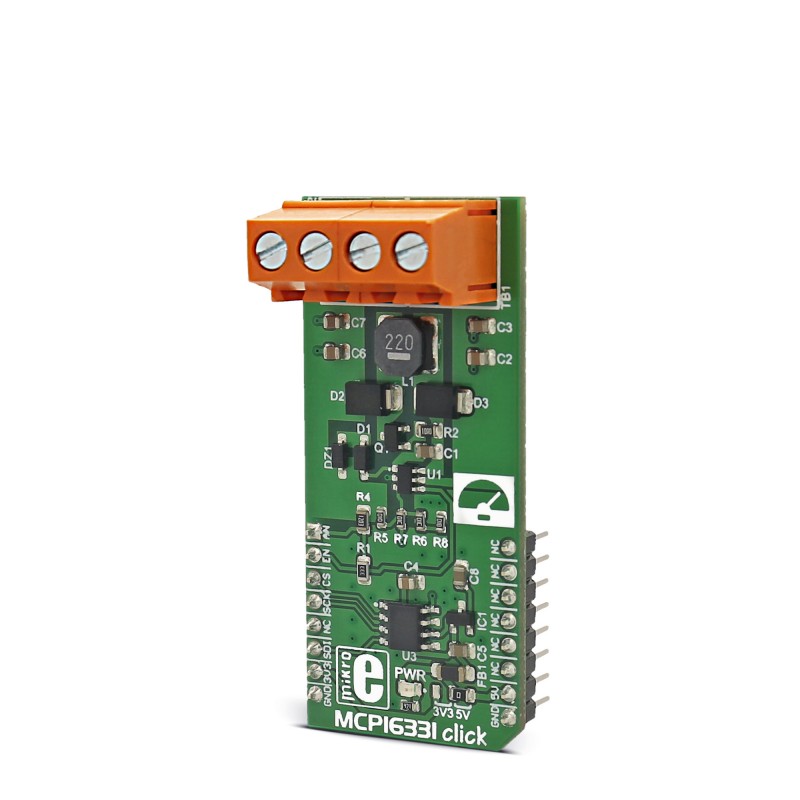
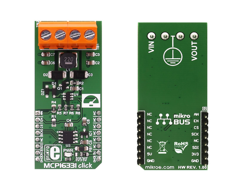
MCP16331 click functions as a non-inverting buck-boost voltage regulator, a type of switching mode power supply topology that combines the principles of the Buck converter (step-down) and the Boost converter (step-up) in a single circuit.
Do you want to subscribe in order to receive notifications regarding "MCP16331 click" changes.
Do you want to unsubscribe in order to stop receiving notifications regarding "MCP16331 click" changes.
Do you want to report abuse regarding "MCP16331 click".
| DOWNLOAD LINK | RELATED COMPILER | CONTAINS |
|---|---|---|
| 1508753646_mcp16631_mikroc_arm.mpkg [350.63KB] | mikroC PRO for ARM |
|
| 1508753673_mcp16631_mikroc_avr.mpkg [153.35KB] | mikroC PRO for AVR |
|
| 1526565828_mcp16331_click_mikroc_dspic.zip [114.31KB] | mikroC PRO for dsPIC30/33 & PIC24 |
|
| 1531393803_mcp16331_click_mikroc_ft90x.zip [113.46KB] | mikroC PRO for FT90x |
|
| 1518534566_mcp16331_click_mikroc_pic.zip [117.85KB] | mikroC PRO for PIC |
|
| 1508753738_mcp16631_mikroc_pic32.mpkg [177.11KB] | mikroC PRO for PIC32 |
|


We provide a library for the MCP16331 click, as well as a demo application (example), developed using MikroElektronika compilers. The demo application can run on all the main MikroElektronika development boards.
Library Description
The library carries a function for controlling the MCP16331 click output alongside with SPI driver initialization function.
Key functions
Examples Description
The application is composed of three sections:
void applicationTask()
{
    mcp16331_setVout( 5000 );
    UART1( "rnOutput Voltage changed to 5V" );
    Delay_ms( 3000 );
    mcp16331_setVout( 12000 );
    UART1( "rnOutput Voltage changed to 12V" );
    Delay_ms( 3000 );
}
The example also carries additional functions for GPIO control which are provided during driver initialization. These functions are necessary and implementation depends on development system used.
Other MikroE Libraries used in the example:
Note
Depending on the development board you are using, you may need the RS232 click or USB-UART click or USB UART 2 click, to connect to your PC. The terminal available in all Mikroelektronika compilers, or any other terminal application of your choice, can be used to read the message.


