TOP Contributors

  1. MIKROE (2784 codes)
  2. Alcides Ramos (403 codes)
  3. Shawon Shahryiar (307 codes)
  4. jm_palomino (130 codes)
  5. Bugz Bensce (97 codes)
  6. S P (73 codes)
  7. dany (71 codes)
  8. MikroBUS.NET Team (35 codes)
  9. NART SCHINACKOW (34 codes)
  10. Armstrong Subero (27 codes)

Most Downloaded

  1. Timer Calculator (140933 times)
  2. FAT32 Library (73497 times)
  3. Network Ethernet Library (58294 times)
  4. USB Device Library (48478 times)
  5. Network WiFi Library (44081 times)
  6. FT800 Library (43652 times)
  7. GSM click (30538 times)
  8. mikroSDK (29259 times)
  9. PID Library (27204 times)
  10. microSD click (26926 times)
Libstock prefers package manager

Package Manager

We strongly encourage users to use Package manager for sharing their code on Libstock website, because it boosts your efficiency and leaves the end user with no room for error. [more info]

< Back
mikroSDK Library

Stepper 7 click

Rating:

5

Author: MIKROE

Last Updated: 2018-02-08

Package Version: 1.0.0.0

mikroSDK Library: 1.0.0.0

Category: Stepper

Downloaded: 5864 times

Not followed.

License: MIT license  

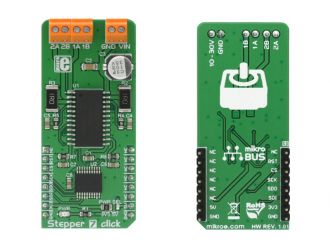
Stepper 7 click is a bipolar step motor driver. It features an H-bridge bipolar step motor driver, which supports full, half and micro-step control modes.

No Abuse Reported

Do you want to subscribe in order to receive notifications regarding "Stepper 7 click" changes.

Do you want to unsubscribe in order to stop receiving notifications regarding "Stepper 7 click" changes.

Do you want to report abuse regarding "Stepper 7 click".
  • mikroSDK Library 2.0.0.0
  • Comments (0)
DOWNLOAD LINK RELATED COMPILER CONTAINS
mikroBasic PRO for ARM
  • lib
  • src
  • exa
  • hlp
  • hex
  • sch
  • pcb
  • doc
mikroBasic PRO for AVR
  • lib
  • src
  • exa
  • hlp
  • hex
  • sch
  • pcb
  • doc
mikroBasic PRO for dsPIC30/33 & PIC24
  • lib
  • src
  • exa
  • hlp
  • hex
  • sch
  • pcb
  • doc
mikroBasic PRO for FT90x
  • lib
  • src
  • exa
  • hlp
  • hex
  • sch
  • pcb
  • doc
mikroBasic PRO for PIC
  • lib
  • src
  • exa
  • hlp
  • hex
  • sch
  • pcb
  • doc
mikroBasic PRO for PIC32
  • lib
  • src
  • exa
  • hlp
  • hex
  • sch
  • pcb
  • doc
mikroC PRO for ARM
  • lib
  • src
  • exa
  • hlp
  • hex
  • sch
  • pcb
  • doc
mikroC PRO for AVR
  • lib
  • src
  • exa
  • hlp
  • hex
  • sch
  • pcb
  • doc
mikroC PRO for dsPIC30/33 & PIC24
  • lib
  • src
  • exa
  • hlp
  • hex
  • sch
  • pcb
  • doc
mikroC PRO for FT90x
  • lib
  • src
  • exa
  • hlp
  • hex
  • sch
  • pcb
  • doc
mikroC PRO for PIC
  • lib
  • src
  • exa
  • hlp
  • hex
  • sch
  • pcb
  • doc
mikroC PRO for PIC32
  • lib
  • src
  • exa
  • hlp
  • hex
  • sch
  • pcb
  • doc
mikroPascal PRO for ARM
  • lib
  • src
  • exa
  • hlp
  • hex
  • sch
  • pcb
  • doc
mikroPascal PRO for AVR
  • lib
  • src
  • exa
  • hlp
  • hex
  • sch
  • pcb
  • doc
mikroPascal PRO for dsPIC30/33 & PIC24
  • lib
  • src
  • exa
  • hlp
  • hex
  • sch
  • pcb
  • doc
mikroPascal PRO for FT90x
  • lib
  • src
  • exa
  • hlp
  • hex
  • sch
  • pcb
  • doc
mikroPascal PRO for PIC
  • lib
  • src
  • exa
  • hlp
  • hex
  • sch
  • pcb
  • doc
mikroPascal PRO for PIC32
  • lib
  • src
  • exa
  • hlp
  • hex
  • sch
  • pcb
  • doc

mikroSDK Library Blog

Stepper 7 click

Stepper 7 click

Native view of the Stepper 7 Click board.

View full image
Stepper 7 click

Stepper 7 click

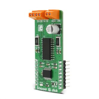
Front and back view of the Stepper 7 Click board.

View full image

Library description

This library carries everything needed for stepper motor control, including speed and acceleration setup. The library can be adjusted to work on the different amount of ticks per second. Also, speed and acceleration can be provided in float format. The buffer used for movement calculation is defined by the user in order that the library can be adjusted for MCUs with very limited RAM resources. Check the documentation for more details how to use it.

Key functions

uint8_t stepper7_setSpeed( float minSpeed, float maxSpeed, float accelRatio, T_STEPPER7_OBJ obj ) - Sets up the motor speed

uint8_t stepper7_setRoute( const uint8_t direction, uint32_t steps, T_STEPPER7_OBJ obj ) - Sets up a new route

void stepper7_start( T_STEPPER7_OBJ obj ) - Starts motor movement

The application is composed of three sections :

  • System Initialization - Initializes all GPIO pins found on Stepper 7 Click and timer to 1ms interrupt.
  • Application Initialization - The first segment initializes driver and stepper control. The second segment sets up movement limits, maximum and minimum speed, and acceleration ratio. The third segment enables motor and sets up the new route which will be called from the application task.
  • Application Task - (code snippet) - Sequentially moves the motor and executes movement until the end.
void applicationTask()
{
    stepper7_start( (T_STEPPER7_OBJ_P)&myStepper );
    while( myStepper.status.running )
        stepper7_process( (T_STEPPER7_OBJ_P)&myStepper );
    Delay_ms( 2000 );
}

In addition to library function calls, example carries necessary Timer ISR and Timer initialization. Check Timer initialization settings and update it according to your MCU - Timer Calculator.
 

Additional notes and information

Depending on the development board you are using, you may need USB UART clickUSB UART 2 click or  RS232 click to connect to your PC, for development systems with no UART to USB interface available on the board. The terminal available in all MikroElektronika compilers, or any other terminal application of your choice, can be used to read the message.

ALSO FROM THIS AUTHOR

Matrix G click

5

Matrix G click is a mikroBUS add-on board with two 5x7 matrices driven by two MAX7219 8-bit LED Display Drivers.

[Learn More]

OBDII Click

0

OBDII Click offers a unique opportunity to tap into the car diagnostic systems. It features the STN1110 Multiprotocol OBD to UART Interface, developed by the ScanTool technologies. This Click can be used for the communication with the Electronic Control Unit (ECU) of a vehicle, via several different OBD II diagnostic protocols such as CAN, K LINE, L LINE and J1850. The STN1110 IC is used to process requests sent by the MCU via the UART interface and return back the responses from the ECU network nodes.

[Learn More]

PWM Click

1

PWM click is a simple solution for controlling 16 PWM outputs through a single I2C interface. The click board carries the PCA9685PW IC. It is designed to use either a 3.3V or 5V power supply. The board also uses a LOW Output Enable Input pin (OE), which is in place of the default mikroBUS RST pin.

[Learn More]