TOP Contributors

  1. MIKROE (2784 codes)
  2. Alcides Ramos (405 codes)
  3. Shawon Shahryiar (307 codes)
  4. jm_palomino (133 codes)
  5. Bugz Bensce (97 codes)
  6. S P (73 codes)
  7. dany (71 codes)
  8. MikroBUS.NET Team (35 codes)
  9. NART SCHINACKOW (34 codes)
  10. Armstrong Subero (27 codes)

Most Downloaded

  1. Timer Calculator (141246 times)
  2. FAT32 Library (74083 times)
  3. Network Ethernet Library (58708 times)
  4. USB Device Library (48814 times)
  5. Network WiFi Library (44523 times)
  6. FT800 Library (44072 times)
  7. GSM click (30802 times)
  8. mikroSDK (29648 times)
  9. PID Library (27355 times)
  10. microSD click (27251 times)
Libstock prefers package manager

Package Manager

We strongly encourage users to use Package manager for sharing their code on Libstock website, because it boosts your efficiency and leaves the end user with no room for error. [more info]

< Back
mikroSDK Library

Gaussmeter click

Rating:

5

Author: MIKROE

Last Updated: 2018-07-18

Package Version: 1.0.0.0

mikroSDK Library: 1.0.0.0

Category: Magnetic

Downloaded: 5510 times

Not followed.

License: MIT license  

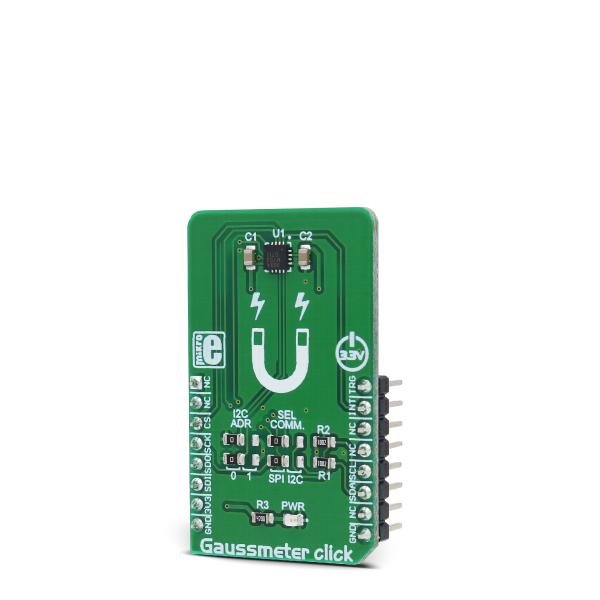
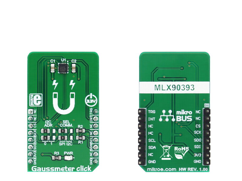
Gaussmeter click is a device that is used for measuring the magnetic field in X, Y and Z axes. This Click board features the MLX90393, a micropower magnetometer based on the proprietary Triaxis technology, from Melexis. It can detect the magnetic field down to 0.8 µT (8 mG) thanks to this technology.

No Abuse Reported

Do you want to subscribe in order to receive notifications regarding "Gaussmeter click" changes.

Do you want to unsubscribe in order to stop receiving notifications regarding "Gaussmeter click" changes.

Do you want to report abuse regarding "Gaussmeter click".

  • mikroSDK Library 2.0.0.0
  • Comments (0)
DOWNLOAD LINK RELATED COMPILER CONTAINS
mikroBasic PRO for ARM
  • lib
  • src
  • exa
  • hlp
  • hex
  • sch
  • pcb
  • doc
mikroBasic PRO for AVR
  • lib
  • src
  • exa
  • hlp
  • hex
  • sch
  • pcb
  • doc
mikroBasic PRO for dsPIC30/33 & PIC24
  • lib
  • src
  • exa
  • hlp
  • hex
  • sch
  • pcb
  • doc
mikroBasic PRO for FT90x
  • lib
  • src
  • exa
  • hlp
  • hex
  • sch
  • pcb
  • doc
mikroBasic PRO for PIC
  • lib
  • src
  • exa
  • hlp
  • hex
  • sch
  • pcb
  • doc
mikroBasic PRO for PIC32
  • lib
  • src
  • exa
  • hlp
  • hex
  • sch
  • pcb
  • doc
mikroC PRO for ARM
  • lib
  • src
  • exa
  • hlp
  • hex
  • sch
  • pcb
  • doc
mikroC PRO for AVR
  • lib
  • src
  • exa
  • hlp
  • hex
  • sch
  • pcb
  • doc
mikroC PRO for dsPIC30/33 & PIC24
  • lib
  • src
  • exa
  • hlp
  • hex
  • sch
  • pcb
  • doc
mikroC PRO for FT90x
  • lib
  • src
  • exa
  • hlp
  • hex
  • sch
  • pcb
  • doc
mikroC PRO for PIC
  • lib
  • src
  • exa
  • hlp
  • hex
  • sch
  • pcb
  • doc
mikroC PRO for PIC32
  • lib
  • src
  • exa
  • hlp
  • hex
  • sch
  • pcb
  • doc
mikroPascal PRO for ARM
  • lib
  • src
  • exa
  • hlp
  • hex
  • sch
  • pcb
  • doc
mikroPascal PRO for AVR
  • lib
  • src
  • exa
  • hlp
  • hex
  • sch
  • pcb
  • doc
mikroPascal PRO for dsPIC30/33 & PIC24
  • lib
  • src
  • exa
  • hlp
  • hex
  • sch
  • pcb
  • doc
mikroPascal PRO for FT90x
  • lib
  • src
  • exa
  • hlp
  • hex
  • sch
  • pcb
  • doc
mikroPascal PRO for PIC
  • lib
  • src
  • exa
  • hlp
  • hex
  • sch
  • pcb
  • doc
mikroPascal PRO for PIC32
  • lib
  • src
  • exa
  • hlp
  • hex
  • sch
  • pcb
  • doc

mikroSDK Library Blog

Gaussmeter click

Gaussmeter click

Native view of the Gaussmeter click board.

View full image
Gaussmeter click

Gaussmeter click

Front and back view of the Gaussmeter clik board.

View full image

Library Description

Library initializes and defines I2C and SPI driver and has the ability to write to registers and read from registers by both driver communication. Library also performs magnetic field measurement via x, y and/or z-axis and converts results to µT. The library can measure 16-bit temperature value. For more details check the documentation.

Key functions 

void gaussmeter_enableMeasure( uint8_t zAxis, uint8_t yAxis, uint8_t xAxis, uint8_t temp ) - Function determines which axis will be included in the measurement.

uint8_t gaussmeter_sendCommand( uint8_t command_ ) - Function performs desired command.

uint8_t gaussmeter_readReg( uint8_t register_address, uint16_t *dataOut ) - Function reads 16-bit data from a register.

uint8_t gaussmeter_writeReg( uint8_t register_address, uint16_t transfer_data ) - Function writes 16-bit data in a register.

uint8_t gaussmeter_getData( uint32_t *dataOut ) - Function gets selected measured data.

Examples Description
The application is composed of three sections :

System Initialization - Initializes peripherals and pins.
Application Initialization - Initializes I2C or SPI driver and performs click configuration.
The device is configured to work in Wake Up On Change mode.
Application Task - (code snippet) - Gets x, y and z-axis measured data (without temperature) in µT.
Logs the desired results on USBUART and repeats measurements every 400ms.


void applicationTask()
{
 errorBit = gaussmeter_getData( &bufferData[ 0 ] );

 if (!errorBit)
 {
 axisCheck = 1;
 indx = 0;

 for (counter = 0; counter < 4; counter++)
 {
 switch (commandByteLow & axisCheck)
 {
 case 1 : 
 {
 mikrobus_logWrite( "16-bit temperature value is: ", _LOG_TEXT );
 LongWordToStr( bufferData[ indx ], text );
 mikrobus_logWrite( text, _LOG_LINE );
 indx++;
 break;
 }
 case 2 : 
 {
 mikrobus_logWrite( "X axis is: ", _LOG_TEXT );
 LongWordToStr( bufferData[ indx ], text );
 mikrobus_logWrite( text, _LOG_TEXT );
 mikrobus_logWrite( "microT", _LOG_LINE );
 indx++;
 break;
 }
 case 4 : 
 {
 mikrobus_logWrite( "Y axis is: ", _LOG_TEXT );
 LongWordToStr( bufferData[ indx ], text );
 mikrobus_logWrite( text, _LOG_TEXT );
 mikrobus_logWrite( "microT", _LOG_LINE );
 indx++;
 break;
 }
 case 8 : 
 {
 mikrobus_logWrite( "Z axis is: ", _LOG_TEXT );
 LongWordToStr( bufferData[ indx ], text );
 mikrobus_logWrite( text, _LOG_TEXT );
 mikrobus_logWrite( "microT", _LOG_LINE );
 indx++;
 break;
 }
 default :
 {
 break;
 }
 }

 axisCheck <<= 1;
 }
 mikrobus_logWrite( "", _LOG_LINE );
 Delay_ms( 400 );
 }
}


Other mikroE Libraries used in the example:

  • Conversions
  • I2C
  • SPI
  • UART

Additional notes and information

Depending on the development board you are using, you may need USB UART clickUSB UART 2 click or RS232 click to connect to your PC, for development systems with no UART to USB interface available on the board. The terminal available in all MikroElektronika compilers, or any other terminal application of your choice, can be used to read the message.

ALSO FROM THIS AUTHOR

N-PLC Click

0

N-PLC Click is a compact add-on board that uses existing electrical power lines to transmit data signals. This board features the SM2400, an advanced multi-standard Narrow-band Power Line Communication (N-PLC) modem from Semitech. The SM2400 features a dual-core architecture, a DSP core for N-PLC modulations, and a 32-bit core for running protocols for superior communication performance and flexibility for various open standards and customized implementations. It includes firmware options for IEEE 1901.2 compliant PHY and MAC layers, a 6LoWPAN data link layer, and special modes for industrial IoT applications. In addition to the ability to accept signals from another PLC modem or the power line communication AC coupling circuit, this board also has a handful of other features, such as a selectable interface and power supply, firmware update capabilities, LED indicators, and many others.

[Learn More]

RTC 17 Click

0

RTC 17 Click is a compact add-on board that accurately keeps the time of a day. This board features the RV5C387A, a CMOS real-time clock with a built-in interrupt generation function from Nisshinbo Micro Devices Inc, to perform serial transmission of time and calendar data to the MCU. The BU9873 provides information like year, month, day, weekday, hours, minutes, and seconds based on a 32.768kHz quartz crystal through an I2C serial interface to transmit time and calendar data to the MCU. It also has an alarm function that outputs an interrupt signal to the MCU when the day of the week, hour, or minute matches with the preset time.

[Learn More]

PWM Click

1

PWM click is a simple solution for controlling 16 PWM outputs through a single I2C interface. The click board carries the PCA9685PW IC. It is designed to use either a 3.3V or 5V power supply. The board also uses a LOW Output Enable Input pin (OE), which is in place of the default mikroBUS RST pin.

[Learn More]