TOP Contributors

  1. MIKROE (2784 codes)
  2. Alcides Ramos (405 codes)
  3. Shawon Shahryiar (307 codes)
  4. jm_palomino (133 codes)
  5. Bugz Bensce (97 codes)
  6. S P (73 codes)
  7. dany (71 codes)
  8. MikroBUS.NET Team (35 codes)
  9. NART SCHINACKOW (34 codes)
  10. Armstrong Subero (27 codes)

Most Downloaded

  1. Timer Calculator (141210 times)
  2. FAT32 Library (73995 times)
  3. Network Ethernet Library (58642 times)
  4. USB Device Library (48764 times)
  5. Network WiFi Library (44458 times)
  6. FT800 Library (44033 times)
  7. GSM click (30784 times)
  8. mikroSDK (29513 times)
  9. PID Library (27339 times)
  10. microSD click (27188 times)
Libstock prefers package manager

Package Manager

We strongly encourage users to use Package manager for sharing their code on Libstock website, because it boosts your efficiency and leaves the end user with no room for error. [more info]

< Back
mikroSDK Library

Color 6 click

Rating:

5

Author: MIKROE

Last Updated: 2018-06-25

Package Version: 1.0.0.0

mikroSDK Library: 1.0.0.0

Category: Optical

Downloaded: 5221 times

Not followed.

License: MIT license  

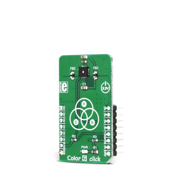
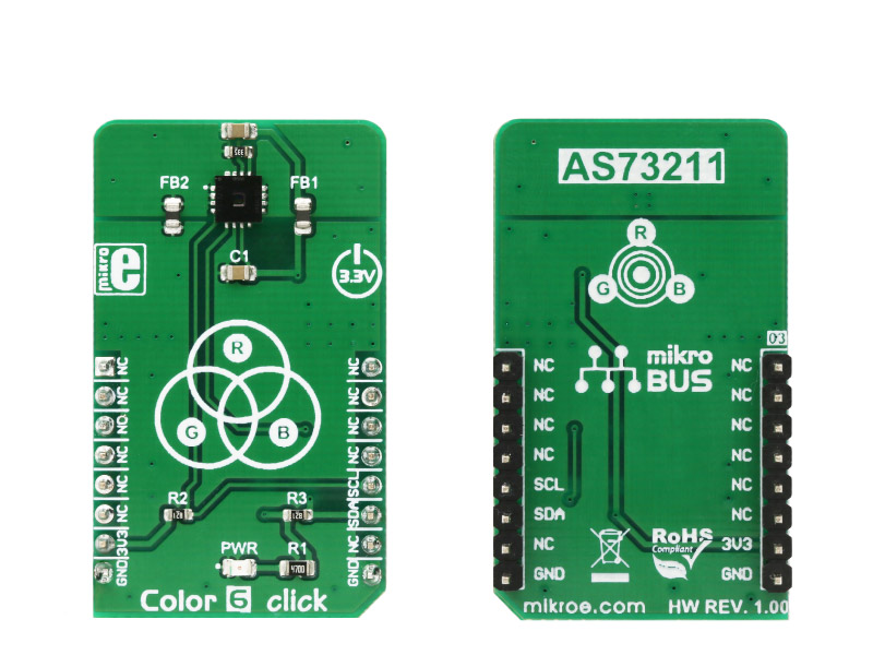
Color 6 click is a very accurate color sensing Click board which features the AS73211, an XYZ true color sensor from ams.

No Abuse Reported

Do you want to subscribe in order to receive notifications regarding "Color 6 click" changes.

Do you want to unsubscribe in order to stop receiving notifications regarding "Color 6 click" changes.

Do you want to report abuse regarding "Color 6 click".

  • mikroSDK Library 2.0.0.0
  • Comments (0)
DOWNLOAD LINK RELATED COMPILER CONTAINS
mikroBasic PRO for ARM
  • lib
  • src
  • exa
  • hlp
  • hex
  • sch
  • pcb
  • doc
mikroBasic PRO for AVR
  • lib
  • src
  • exa
  • hlp
  • hex
  • sch
  • pcb
  • doc
mikroBasic PRO for dsPIC30/33 & PIC24
  • lib
  • src
  • exa
  • hlp
  • hex
  • sch
  • pcb
  • doc
mikroBasic PRO for FT90x
  • lib
  • src
  • exa
  • hlp
  • hex
  • sch
  • pcb
  • doc
mikroBasic PRO for PIC
  • lib
  • src
  • exa
  • hlp
  • hex
  • sch
  • pcb
  • doc
mikroBasic PRO for PIC32
  • lib
  • src
  • exa
  • hlp
  • hex
  • sch
  • pcb
  • doc
mikroC PRO for ARM
  • lib
  • src
  • exa
  • hlp
  • hex
  • sch
  • pcb
  • doc
mikroC PRO for AVR
  • lib
  • src
  • exa
  • hlp
  • hex
  • sch
  • pcb
  • doc
mikroC PRO for dsPIC30/33 & PIC24
  • lib
  • src
  • exa
  • hlp
  • hex
  • sch
  • pcb
  • doc
mikroC PRO for FT90x
  • lib
  • src
  • exa
  • hlp
  • hex
  • sch
  • pcb
  • doc
mikroC PRO for PIC
  • lib
  • src
  • exa
  • hlp
  • hex
  • sch
  • pcb
  • doc
mikroC PRO for PIC32
  • lib
  • src
  • exa
  • hlp
  • hex
  • sch
  • pcb
  • doc
mikroPascal PRO for ARM
  • lib
  • src
  • exa
  • hlp
  • hex
  • sch
  • pcb
  • doc
mikroPascal PRO for AVR
  • lib
  • src
  • exa
  • hlp
  • hex
  • sch
  • pcb
  • doc
mikroPascal PRO for dsPIC30/33 & PIC24
  • lib
  • src
  • exa
  • hlp
  • hex
  • sch
  • pcb
  • doc
mikroPascal PRO for FT90x
  • lib
  • src
  • exa
  • hlp
  • hex
  • sch
  • pcb
  • doc
mikroPascal PRO for PIC
  • lib
  • src
  • exa
  • hlp
  • hex
  • sch
  • pcb
  • doc
mikroPascal PRO for PIC32
  • lib
  • src
  • exa
  • hlp
  • hex
  • sch
  • pcb
  • doc

mikroSDK Library Blog

Color 6 click

Color 6 click

Native view of the Color 6 click board.

View full image
Color 6 click

Color 6 click

Front and back view of the Color 6 click board.

View full image

Library Description

The library initializes and defines the I2C bus driver and drivers that offer a choice for writing data in the register. The library includes the function for configuration chip for measurement, functions for reading temperature, channel (X or Y or Z) data. The user also has the function float color6_convertingToEe(uint8_t channel, uint16_t MRES_data) which converts channel data to Ee (Input light irradiance regarding to the photodiode’s area within the conversion time interval) data.

Key functions:

  • uint16_t color6_readData(uint8_t reg) - Functions for reading data from register
  • float color6_convertingToEe(uint8_t channel, uint16_t MRES_data) - Functions for converting channel data to Ee data.
  • void color6_goToMeasurementMode() - Functions for go to measurement mode.
  • float color6_getTemperature() - Functions for reading temperature in ℃.

Example description

The application is composed of three sections:

  • System Initialization - Initializes I2C module.
  • Application Initialization - Initializes driver init and configuration chip for measurement.
  • Application Task - (code snippet) - Reads values from the X / Y / Z channel and converts to Ee (input light irradiance regarding the photodiode’s area within the conversion time interval) data. This data logs on USB UART every 2 seconds.
void applicationTask()
{
 mikrobus_logWrite(" Channel X : ",_LOG_TEXT);
 X_data = color6_readData(_COLOR6_MREG_MEASUREMENT_X_CHANNEL );
 IntToStr(X_data, dataText);
 mikrobus_logWrite(dataText, _LOG_LINE);

 mikrobus_logWrite(" Ee X channel data: ",_LOG_TEXT);
 Ee_data = color6_convertingToEe(_COLOR6_MREG_MEASUREMENT_X_CHANNEL, X_data);
 FloatToStr(Ee_data, dataText);
 mikrobus_logWrite(dataText, _LOG_LINE);

 mikrobus_logWrite(" Channel Y : ",_LOG_TEXT);
 Y_data = color6_readData(_COLOR6_MREG_MEASUREMENT_Y_CHANNEL );
 IntToStr(Y_data, dataText);
 mikrobus_logWrite(dataText, _LOG_LINE);

 mikrobus_logWrite(" Ee Y channel data: ",_LOG_TEXT);
 Ee_data = color6_convertingToEe(_COLOR6_MREG_MEASUREMENT_Y_CHANNEL, Y_data);
 FloatToStr(Ee_data, dataText);
 mikrobus_logWrite(dataText, _LOG_LINE);

 mikrobus_logWrite(" Channel Z : ",_LOG_TEXT);
 Z_data = color6_readData(_COLOR6_MREG_MEASUREMENT_Z_CHANNEL );
 IntToStr(Z_data, dataText);
 mikrobus_logWrite(dataText, _LOG_LINE);

 mikrobus_logWrite(" Ee Z channel data: ",_LOG_TEXT);
 Ee_data = color6_convertingToEe(_COLOR6_MREG_MEASUREMENT_Z_CHANNEL, Z_data);
 FloatToStr(Ee_data, dataText);
 mikrobus_logWrite(dataText, _LOG_LINE);

 mikrobus_logWrite(" Temperature : ",_LOG_TEXT);
 temperature = color6_getTemperature();
 FloatToStr(temperature, dataText);
 mikrobus_logWrite(dataText, _LOG_LINE);

 mikrobus_logWrite(" ",_LOG_LINE);
 Delay_ms( 2000 );
}


Other MikroElektronika libraries used in the example:

  • Conversions
  • I2C
  • UART

Additional notes and information

Depending on the development board you are using, you may need USB UART clickUSB UART 2 click or RS232 click to connect to your PC, for development systems with no UART to USB interface available on the board. The terminal available in all MikroElektronika compilers, or any other terminal application of your choice, can be used to read the message.

ALSO FROM THIS AUTHOR

Motion 4 Click

0

Motion 4 Click is a long distance PaPIR's motion sensor with plastic lense and controllable output. This Click board features EKMC1603111, a PIR motion sensor from Panasonic Corporation which can be used as human motion detector and is able to detect movement up to 12m with 170uA current consumption. Also featured on Motion 4 Click bord is TLP241A photorelay from Toshiba that is used to provide a reinforced galvanic isolation for the external signals used to drive some external high power electronic equipment when motion is detected. It's allowing up to 40V between the SSR contacts in OFF state, and currents up to 2A while in ON state, thanks to a very low ON-state resistance. Motion 4 Click board™ is supported by a mikroSDK compliant library, which includes functions that simplify software development. This Click board™ comes as a fully tested product, ready to be used on a system equipped with the mikroBUS™ socket.

[Learn More]

RTC 10 click

5

RTC 10 Click is a real time clock module which has an extremely low power consumption, allowing it to be used with a single button cell battery, for an extended period of time. It features the DS3231M, a low-cost, extremely accurate, I2C realtime clock (RTC) from Maxim Integrated.

[Learn More]

Clock Gen 6 Click

0

Clock Gen 6 Click is a compact add-on board representing a digital oscillator solution. This board features the MIC1557, an IttyBitty CMOS RC oscillator designed to provide rail-to-rail pulses for precise time delay or frequency generation from Microchip Technology. The MIC1557 has a single threshold and trigger connection, internally connected, for astable (oscillator) operation only. It also has an enable/reset control signal routed to the RST pin of the mikroBUS™ socket, which controls the bias supply to the oscillator’s internal circuitry and optimizes power consumption used for oscillator power ON/OFF purposes. In addition, it provides the ability to select the desired frequency programmed via a digital potentiometer, the MAX5401.

[Learn More]