TOP Contributors

  1. MIKROE (2745 codes)
  2. Alcides Ramos (371 codes)
  3. Shawon Shahryiar (307 codes)
  4. jm_palomino (118 codes)
  5. Bugz Bensce (90 codes)
  6. S P (73 codes)
  7. dany (71 codes)
  8. MikroBUS.NET Team (35 codes)
  9. NART SCHINACKOW (34 codes)
  10. Armstrong Subero (27 codes)

Most Downloaded

  1. Timer Calculator (138914 times)
  2. FAT32 Library (71500 times)
  3. Network Ethernet Library (56914 times)
  4. USB Device Library (47269 times)
  5. Network WiFi Library (42993 times)
  6. FT800 Library (42282 times)
  7. GSM click (29724 times)
  8. mikroSDK (27668 times)
  9. PID Library (26828 times)
  10. microSD click (26087 times)
Libstock prefers package manager

Package Manager

We strongly encourage users to use Package manager for sharing their code on Libstock website, because it boosts your efficiency and leaves the end user with no room for error. [more info]

< Back
Example

V to Hz 2 click

Rating:

5

Author: MIKROE

Last Updated: 2018-08-20

Package Version: 1.0.0.0

Example: 1.0.0.0

Category: Measurements

Downloaded: 3542 times

Not followed.

License: MIT license  

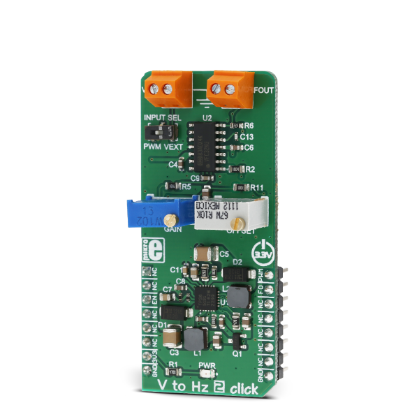
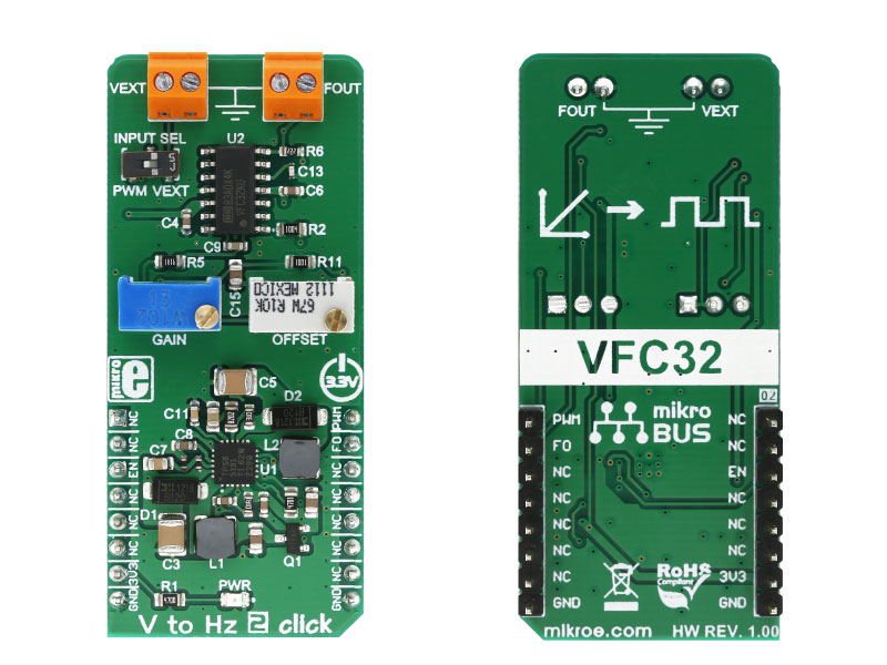
V to Hz 2 click is a device that converts an analog voltage input signal into a pulse wave signal of a certain frequency.

No Abuse Reported

Do you want to subscribe in order to receive notifications regarding "V to Hz 2 click" changes.

Do you want to unsubscribe in order to stop receiving notifications regarding "V to Hz 2 click" changes.

Do you want to report abuse regarding "V to Hz 2 click".

  • mikroSDK Library 2.0.0.0
  • Comments (0)
DOWNLOAD LINK RELATED COMPILER CONTAINS
mikroBasic PRO for ARM
  • lib
  • src
  • exa
  • hlp
  • hex
  • sch
  • pcb
  • doc
mikroBasic PRO for AVR
  • lib
  • src
  • exa
  • hlp
  • hex
  • sch
  • pcb
  • doc
mikroBasic PRO for dsPIC30/33 & PIC24
  • lib
  • src
  • exa
  • hlp
  • hex
  • sch
  • pcb
  • doc
mikroBasic PRO for FT90x
  • lib
  • src
  • exa
  • hlp
  • hex
  • sch
  • pcb
  • doc
mikroBasic PRO for PIC
  • lib
  • src
  • exa
  • hlp
  • hex
  • sch
  • pcb
  • doc
mikroBasic PRO for PIC32
  • lib
  • src
  • exa
  • hlp
  • hex
  • sch
  • pcb
  • doc
mikroC PRO for ARM
  • lib
  • src
  • exa
  • hlp
  • hex
  • sch
  • pcb
  • doc
mikroC PRO for AVR
  • lib
  • src
  • exa
  • hlp
  • hex
  • sch
  • pcb
  • doc
mikroC PRO for dsPIC30/33 & PIC24
  • lib
  • src
  • exa
  • hlp
  • hex
  • sch
  • pcb
  • doc
mikroC PRO for FT90x
  • lib
  • src
  • exa
  • hlp
  • hex
  • sch
  • pcb
  • doc
mikroC PRO for PIC
  • lib
  • src
  • exa
  • hlp
  • hex
  • sch
  • pcb
  • doc
mikroC PRO for PIC32
  • lib
  • src
  • exa
  • hlp
  • hex
  • sch
  • pcb
  • doc
mikroPascal PRO for ARM
  • lib
  • src
  • exa
  • hlp
  • hex
  • sch
  • pcb
  • doc
mikroPascal PRO for AVR
  • lib
  • src
  • exa
  • hlp
  • hex
  • sch
  • pcb
  • doc
mikroPascal PRO for dsPIC30/33 & PIC24
  • lib
  • src
  • exa
  • hlp
  • hex
  • sch
  • pcb
  • doc
mikroPascal PRO for FT90x
  • lib
  • src
  • exa
  • hlp
  • hex
  • sch
  • pcb
  • doc
mikroPascal PRO for PIC
  • lib
  • src
  • exa
  • hlp
  • hex
  • sch
  • pcb
  • doc
mikroPascal PRO for PIC32
  • lib
  • src
  • exa
  • hlp
  • hex
  • sch
  • pcb
  • doc

Example Blog

V to Hz 2 click

V to Hz 2 click

Native view of the V to Hz 2 click board.

View full image
V to Hz 2 click

V to Hz 2 click

Front and back view of the V to Hz 2 click board.

View full image

Library Description

Library initializes and defines GPIO driver and performs commands that can enable or disable the device and get frequency (FOUT) by getting the state of the INT pin. For more details check the documentation.

Key functions :

  • void vtohz2_enable( uint8_t state ) - The function performs enabling and disabling of the device.
  • uint8_t vtohz2_getFreqOut( void ) - The function gets the out frequency on mikrobus INT pin.

Example description

The application is composed of three sections:

  • System Initialization - Initializes peripherals and pins.
  • Application Initialization - Initializes GPIO driver, performs the device enable and sets the pwm frequency. Also writes help with the possible instructions.
  • Application Task - (code snippet) - Checks which command be entered on UART and sets the pwm duty cycle depending on the entered command.
void applicationTask()
{
 if (UART_Rdy_Ptr())
 {
 rxDat = UART_Rd_Ptr();

 if ((rxDat == '+') && (percCheck < 100))
 {
 pwmDutySum += onePercPwm;
 percCheck += 1;
 }
 else if ((rxDat == '-') && (percCheck > 0))
 {
 pwmDutySum -= onePercPwm;
 percCheck -= 1;
 }
 else if ((rxDat == '*') && (percCheck <= 90))
 {
 pwmDutySum += tenPercPwm;
 percCheck += 10;
 }
 else if ((rxDat == '/') && (percCheck >= 10))
 {
 pwmDutySum -= tenPercPwm;
 percCheck -= 10;
 }
 else if (rxDat == 'h')
 {
 vtohz2_writeHelp();
 }

 pwmDuty = pwmDutySum;
 vtohz2_setSpeed( pwmDuty );

 mikrobus_logWrite( "PWM Duty is : ", _LOG_TEXT );
 WordToStr( percCheck, text );
 mikrobus_logWrite( text, _LOG_TEXT );
 mikrobus_logWrite( " %", _LOG_LINE );
 }
}

Additional functions :

  • void vtohz2_writeHelp() - Writes instructions that perform the determined commands.
  • void vtohz2_setSpeed( uint16_t pwm_duty ) - Determines the desired pwm duty cycle and checks the limit of the pwm duty.
  • void vtohz2_pwmInit( uint32_t pwm_freq ) - Initializes the PWM with the desired frequency and calculates the maximal value of the pwm duty cycle.


Other mikroE Libraries used in the example:

  • Conversions
  • PWM
  • UART

Additional notes and information

Depending on the development board you are using, you may need USB UART clickUSB UART 2 click or RS232 click to connect to your PC, for development systems with no UART to USB interface available on the board. The terminal available in all MikroElektronika compilers, or any other terminal application of your choice, can be used to read the message.

ALSO FROM THIS AUTHOR

4G LTE click

6

4G LTE-E click carries the LARA-R211 multi-mode cellular module from u-blox. The board is designed to use 5V power supply. I/O voltage levels could be 3.3V or 5V. It communicates with the target microcontroller over UART interface

[Learn More]

BarGraph 3 click

6

BarGraph 3 click is equipped with a five-segment LED bar graph display, notable for its strong and reliable illumination of the segments.

[Learn More]

SPI Isolator 3 click

0

SPI Isolator 3 Click is a compact add-on board that contains a digital isolator optimized for a serial peripheral interface. This board features the MAX14483, a 6-channel 3.75kVRMS digital galvanic isolator with a very low propagation delay on the SDI, SDO, and SCLK channels from Maxim Integrated. Besides a second enable control input, which allows MAX14483 to isolate multiple SPI devices, and an auxiliary channel available for passing timing or control signals from the master side to the slave side, the MAX14483 also possesses power monitors provided for both power domains to signal if the opposite side of the isolator is ready for operation.

[Learn More]