TOP Contributors

  1. MIKROE (2784 codes)
  2. Alcides Ramos (405 codes)
  3. Shawon Shahryiar (307 codes)
  4. jm_palomino (133 codes)
  5. Bugz Bensce (97 codes)
  6. S P (73 codes)
  7. dany (71 codes)
  8. MikroBUS.NET Team (35 codes)
  9. NART SCHINACKOW (34 codes)
  10. Armstrong Subero (27 codes)

Most Downloaded

  1. Timer Calculator (141361 times)
  2. FAT32 Library (74205 times)
  3. Network Ethernet Library (58777 times)
  4. USB Device Library (48854 times)
  5. Network WiFi Library (44564 times)
  6. FT800 Library (44149 times)
  7. GSM click (30883 times)
  8. mikroSDK (29739 times)
  9. PID Library (27372 times)
  10. microSD click (27309 times)
Libstock prefers package manager

Package Manager

We strongly encourage users to use Package manager for sharing their code on Libstock website, because it boosts your efficiency and leaves the end user with no room for error. [more info]

< Back
mikroSDK Library

LTE IoT 2 click

Rating:

5

Author: MIKROE

Last Updated: 2018-09-07

Package Version: 1.0.0.0

mikroSDK Library: 1.0.0.0

Category: LTE IoT

Downloaded: 6278 times

Not followed.

License: MIT license  

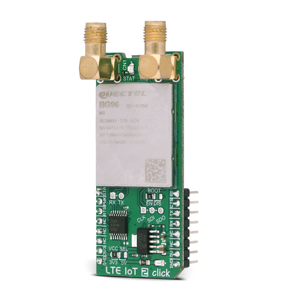
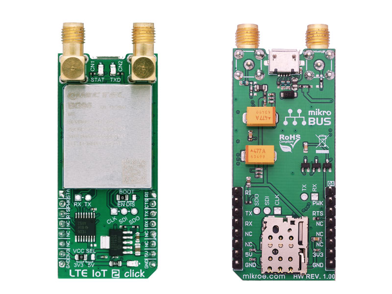
LTE IoT 2 click is a Click board that allows connection to the LTE networks, featuring Quectel BG96 LTE module, which offers two LTE technologies aimed at Machine to Machine communication (M2M) and Internet of Things (IoT).

No Abuse Reported

Do you want to subscribe in order to receive notifications regarding "LTE IoT 2 click" changes.

Do you want to unsubscribe in order to stop receiving notifications regarding "LTE IoT 2 click" changes.

Do you want to report abuse regarding "LTE IoT 2 click".

  • mikroSDK Library 2.0.0.0
  • Comments (0)
DOWNLOAD LINK RELATED COMPILER CONTAINS
mikroBasic PRO for ARM
  • lib
  • src
  • exa
  • hlp
  • hex
  • sch
  • pcb
  • doc
mikroBasic PRO for AVR
  • lib
  • src
  • exa
  • hlp
  • hex
  • sch
  • pcb
  • doc
mikroBasic PRO for dsPIC30/33 & PIC24
  • lib
  • src
  • exa
  • hlp
  • hex
  • sch
  • pcb
  • doc
mikroBasic PRO for FT90x
  • lib
  • src
  • exa
  • hlp
  • hex
  • sch
  • pcb
  • doc
mikroBasic PRO for PIC
  • lib
  • src
  • exa
  • hlp
  • hex
  • sch
  • pcb
  • doc
mikroBasic PRO for PIC32
  • lib
  • src
  • exa
  • hlp
  • hex
  • sch
  • pcb
  • doc
mikroC PRO for ARM
  • lib
  • src
  • exa
  • hlp
  • hex
  • sch
  • pcb
  • doc
mikroC PRO for AVR
  • lib
  • src
  • exa
  • hlp
  • hex
  • sch
  • pcb
  • doc
mikroC PRO for dsPIC30/33 & PIC24
  • lib
  • src
  • exa
  • hlp
  • hex
  • sch
  • pcb
  • doc
mikroC PRO for FT90x
  • lib
  • src
  • exa
  • hlp
  • hex
  • sch
  • pcb
  • doc
mikroC PRO for PIC
  • lib
  • src
  • exa
  • hlp
  • hex
  • sch
  • pcb
  • doc
mikroC PRO for PIC32
  • lib
  • src
  • exa
  • hlp
  • hex
  • sch
  • pcb
  • doc
mikroPascal PRO for ARM
  • lib
  • src
  • exa
  • hlp
  • hex
  • sch
  • pcb
  • doc
mikroPascal PRO for AVR
  • lib
  • src
  • exa
  • hlp
  • hex
  • sch
  • pcb
  • doc
mikroPascal PRO for dsPIC30/33 & PIC24
  • lib
  • src
  • exa
  • hlp
  • hex
  • sch
  • pcb
  • doc
mikroPascal PRO for FT90x
  • lib
  • src
  • exa
  • hlp
  • hex
  • sch
  • pcb
  • doc
mikroPascal PRO for PIC
  • lib
  • src
  • exa
  • hlp
  • hex
  • sch
  • pcb
  • doc
mikroPascal PRO for PIC32
  • lib
  • src
  • exa
  • hlp
  • hex
  • sch
  • pcb
  • doc

mikroSDK Library Blog

LTE IoT 2 click

LTE IoT 2 click

Native view of the LTE IoT 2 click board.

View full image
LTE IoT 2 click

LTE IoT 2 click

Front and back view of the LTE IoT 2 click board.

View full image

The library carries generic command parser adopted for AT command based modules. 
Generic parser

Key functions:

  • lteiot2_cmdSingle - Sends provided command to the module
  • lteiot2_setHandler - Handler assignation to the provied command
  • lteiot2_modulePower - Turn on module

Example description

The application is composed of three sections:

  • System Initialization - Initializes all necessary GPIO pins, UART used for
    the communication with LTE IOT 2 module and UART used for information logging
  • Application Initialization - Initializes driver, power on the module and sends few
    commands for the default module configuration
  • Application Task Sends a message to Quectel NB-IoT test server(bit.ly/quectel-udp-server) every 5 sec.

This code snippet shows how generic parser should be properly initialized. Before initialization module must be turned on and add to that hardware flow control should be also 

Commands :
Command: ATI, product information
Command: AT+IPR=115200;&W, set baudrate 
Command: AT+QCFG="nbsibscramble",0, Enable scrambling
Command: AT+QCFG="band",0,0,80,1, set baud
Command: AT+QCFG="nwscanmode",3,1, Set LTE mode
Command: AT+QCFG="nwscanseq",030201,1, set priority NB1 > M1 > 2G
Command: AT+QCFG="iotopmode",1,1, select CAT-NB1
Command: AT+QCFG="servicedomain",1,1, Set PS domain
Command: AT+CGDCONT=1,"IP","internet", set APN provided
Command: AT+CFUN=1, Full functionality
Command: AT+COPS=1,2,"22001",0, set MCC and MNC provided
Command: AT+QIACT=1, activate PDP context
Command: AT+QIOPEN=1,0,"UDP","79.114.83.116",16666, create an UDP socket
Command: AT+QISENDEX=0,"48656C6C6F", Send message - Hello


void applicationInit()
{
// MODULE POWER ON
 lteiot2_hfcEnable( true );
 lteiot2_modulePower( true );

// MODULE INIT
 lteiot2_cmdSingle( &ATI[0] );
 lteiot2_cmdSingle( &AT_IPR[0] );
 lteiot2_cmdSingle( &AT_QCFG_1[0] );
 lteiot2_cmdSingle( &AT_QCFG_2[0] );
 lteiot2_cmdSingle( &AT_QCFG_3[0] );
 lteiot2_cmdSingle( &AT_QCFG_4[0] );
 lteiot2_cmdSingle( &AT_QCFG_5[0] );
 lteiot2_cmdSingle( &AT_QCFG_6[0] );
 lteiot2_cmdSingle( &AT_CGDCONT[0] );
 lteiot2_cmdSingle( &AT_CFUN[0] );
 lteiot2_cmdSingle( &AT_COPS[0] );
 lteiot2_cmdSingle( &AT_CGATT[0] );
 lteiot2_cmdSingle( &AT_CEREG[0] );
 lteiot2_cmdSingle( &AT_QIACT[0] );
 lteiot2_cmdSingle( &AT_QIOPEN[0] );
 lteiot2_cmdSingle( &AT_QISENDEX[0] );
}

Alongside with the demo application timer initialization functions are provided. Note that timer is configured acording to default development system and MCUs, changing the system or MCU may require an update of timer init and timer ISR functions.

Other MikroElektronika libraries used in the example:

  • String
  • Conversion

Additional notes and information

Depending on the development board you are using, you may need USB UART clickUSB UART 2 clickor RS232 click to connect to your PC, for development systems with no UART to USB interface available on the board. The terminal available in all MikroElektronika compilers, or any other terminal application of your choice, can be used to read the message.

ALSO FROM THIS AUTHOR

PAC1921 Click

0

PAC1921 Click is a versatile power monitoring and measuring device intended for the high speed, low latency measurements. This device can measure current, voltage or the power of the connected load.

[Learn More]

UT-S 7-SEG R Click

0

7-segment LED display is the most commonly used type of display to represent changing numerical values. The principle is very simple - seven LED segments are positioned in a certain shape and by turning specific segments on or off, the shape that resembles a specific number is lit. This method of displaying numbers was first used in the beginning of the 20th century, but after the invention of the LED in ‘70, it is the most commonly used method to display numbers. It utilizes a fairly simple and cheap design with the numbers clearly visible.

[Learn More]

LED Driver 4 Click

0

LED Driver 4 Click is a form of a high-efficiency boost converter that is ideally suited for driving an array of white LEDs. The driver has the ability to dim the connected LED array, without producing any noise on the output. The Click board is capable of driving a LED array with up to 26V, providing a constant current to the LED segments.

[Learn More]