TOP Contributors

  1. MIKROE (2784 codes)
  2. Alcides Ramos (392 codes)
  3. Shawon Shahryiar (307 codes)
  4. jm_palomino (123 codes)
  5. Bugz Bensce (97 codes)
  6. S P (73 codes)
  7. dany (71 codes)
  8. MikroBUS.NET Team (35 codes)
  9. NART SCHINACKOW (34 codes)
  10. Armstrong Subero (27 codes)

Most Downloaded

  1. Timer Calculator (140553 times)
  2. FAT32 Library (73048 times)
  3. Network Ethernet Library (58051 times)
  4. USB Device Library (48223 times)
  5. Network WiFi Library (43833 times)
  6. FT800 Library (43295 times)
  7. GSM click (30360 times)
  8. mikroSDK (28993 times)
  9. PID Library (27119 times)
  10. microSD click (26722 times)
Libstock prefers package manager

Package Manager

We strongly encourage users to use Package manager for sharing their code on Libstock website, because it boosts your efficiency and leaves the end user with no room for error. [more info]

< Back
mikroSDK Library

Boost-INV click

Rating:

5

Author: MIKROE

Last Updated: 2018-08-15

Package Version: 1.0.0.0

mikroSDK Library: 1.0.0.0

Category: Boost

Downloaded: 4391 times

Not followed.

License: MIT license  

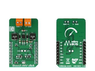
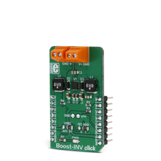
Boost-INV click is a very useful DC/DC voltage converter device, as can output both positive and negative voltage, boosted up to 12.78V and -13.95, from a single fixed voltage input.

No Abuse Reported

Do you want to subscribe in order to receive notifications regarding "Boost-INV click" changes.

Do you want to unsubscribe in order to stop receiving notifications regarding "Boost-INV click" changes.

Do you want to report abuse regarding "Boost-INV click".
  • mikroSDK Library 2.0.0.0
  • Comments (0)
DOWNLOAD LINK RELATED COMPILER CONTAINS
mikroBasic PRO for ARM
  • lib
  • src
  • exa
  • hlp
  • hex
  • sch
  • pcb
  • doc
mikroBasic PRO for AVR
  • lib
  • src
  • exa
  • hlp
  • hex
  • sch
  • pcb
  • doc
mikroBasic PRO for dsPIC30/33 & PIC24
  • lib
  • src
  • exa
  • hlp
  • hex
  • sch
  • pcb
  • doc
mikroBasic PRO for FT90x
  • lib
  • src
  • exa
  • hlp
  • hex
  • sch
  • pcb
  • doc
mikroBasic PRO for PIC
  • lib
  • src
  • exa
  • hlp
  • hex
  • sch
  • pcb
  • doc
mikroBasic PRO for PIC32
  • lib
  • src
  • exa
  • hlp
  • hex
  • sch
  • pcb
  • doc
mikroC PRO for ARM
  • lib
  • src
  • exa
  • hlp
  • hex
  • sch
  • pcb
  • doc
mikroC PRO for AVR
  • lib
  • src
  • exa
  • hlp
  • hex
  • sch
  • pcb
  • doc
mikroC PRO for dsPIC30/33 & PIC24
  • lib
  • src
  • exa
  • hlp
  • hex
  • sch
  • pcb
  • doc
mikroC PRO for FT90x
  • lib
  • src
  • exa
  • hlp
  • hex
  • sch
  • pcb
  • doc
mikroC PRO for PIC
  • lib
  • src
  • exa
  • hlp
  • hex
  • sch
  • pcb
  • doc
mikroC PRO for PIC32
  • lib
  • src
  • exa
  • hlp
  • hex
  • sch
  • pcb
  • doc
mikroPascal PRO for ARM
  • lib
  • src
  • exa
  • hlp
  • hex
  • sch
  • pcb
  • doc
mikroPascal PRO for AVR
  • lib
  • src
  • exa
  • hlp
  • hex
  • sch
  • pcb
  • doc
mikroPascal PRO for dsPIC30/33 & PIC24
  • lib
  • src
  • exa
  • hlp
  • hex
  • sch
  • pcb
  • doc
mikroPascal PRO for FT90x
  • lib
  • src
  • exa
  • hlp
  • hex
  • sch
  • pcb
  • doc
mikroPascal PRO for PIC
  • lib
  • src
  • exa
  • hlp
  • hex
  • sch
  • pcb
  • doc
mikroPascal PRO for PIC32
  • lib
  • src
  • exa
  • hlp
  • hex
  • sch
  • pcb
  • doc

mikroSDK Library Blog

Boost-INV click

Boost-INV click

Native view of the Boost-INV click board.

View full image
Boost-INV click

Boost-INV click

Front and back view of the Boost-INV click board.

View full image

Library Description

Library initializes and defines I2C bus driver and driver functions which offer a choice to write data in registers and to read data from registers. The library includes the function for sets positive and negative output voltage and function for enable chip. The user has to set a positive voltage from 3200mV to 12750mV with a step of 50mV and set the negative voltage from -1200mV to -13950mV with a step of 50mV.

Key functions :

  • void boostinv_setPositiveVoltage(uint16_t voltage) - Functions which set the positive output voltage
  • void boostinv_setNegativeVoltage(int16_t voltage) - Functions which set the negative output voltage
  • void boostinv_enable() - Functions for enable chip

Example description

The application is composed of three sections :

  • System Initialization - Initializes I2C module and sets the RST pin as the OUTPUT
  • Application Initialization - Initializes the Driver, enables chip and selects programming registers
  • Application Task - (code snippet) - Changes the positive and negative output voltage. Positive output voltage goes from 3200mV to 12750mV with a step of 50mV Negative output voltage goes from -1200mV to -13950mV with a step of 50mV
void applicationTask()
{
// Sets Positive output voltage
 Positive_Vout = 3200;
 boostinv_setPositiveVoltage(Positive_Vout);
 Delay_ms( 5000 );
 Positive_Vout = 7750;
 boostinv_setPositiveVoltage(Positive_Vout);
 Delay_ms( 5000 );
 Positive_Vout = 12000;
 boostinv_setPositiveVoltage(Positive_Vout);
 Delay_ms( 5000 );
 Positive_Vout = 7750;
 boostinv_setPositiveVoltage(Positive_Vout);
 Delay_ms( 5000 );
// Sets Negative output voltage
 Negative_Vout = -1450;
 boostinv_setNegativeVoltage(Negative_Vout);
 Delay_ms( 5000 );
 Negative_Vout = -6700;
 boostinv_setNegativeVoltage(Negative_Vout);
 Delay_ms( 5000 );
 Negative_Vout = -11050;
 boostinv_setNegativeVoltage(Negative_Vout);
 Delay_ms( 5000 );
 Negative_Vout = -6700;
 boostinv_setNegativeVoltage(Negative_Vout);
 Delay_ms( 5000 );
}


Other mikroE Libraries used in the example:

  • I2C

Additional notes and information

Depending on the development board you are using, you may need USB UART clickUSB UART 2 click or RS232 click to connect to your PC, for development systems with no UART to USB interface available on the board. The terminal available in all MikroElektronika compilers, or any other terminal application of your choice, can be used to read the message.

ALSO FROM THIS AUTHOR

ISM 5 Click

0

ISM 5 Click is a compact add-on board designed for seamless integration into a wide range of applications requiring efficient communication in the Sub-GHz 868MHz frequency band. This board features the Si4461, a high-performance, low-current transceiver from Silicon Labs known for its robust operation in time division duplexing (TDD) mode, enabling alternating transmission and reception of data packets.

[Learn More]

16x9 G click

5

16x9 G click contains a green LED matrix and the IS31FL3731 audio modulated matrix LED driver. The dimension of the LED matrix is 16x9. Each LED can be controlled individually – both for on/off control and light intensity.

[Learn More]

Brushless click

0

Brushless click carries Toshiba's TB6575FNG IC for driving 3-phase full-wave Brushless DC motors. The click is able to safely drive external motors with up to 32V/2A.Brushless click communicates with the target board MCU over the PWM pin, as well as INT, AN and RST pins. The board is designed to use a 5V power supply only.

[Learn More]