
We strongly encourage users to use Package manager for sharing their code on Libstock website, because it boosts your efficiency and leaves the end user with no room for error. [more info]

Rating:
Author: MIKROE
Last Updated: 2018-09-27
Package Version: 1.0.0.0
mikroSDK Library: 1.0.0.0
Category: Measurements
Downloaded: 6025 times
Not followed.
License: MIT license
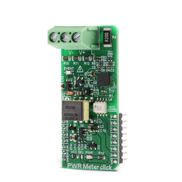
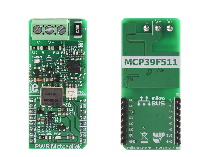
PWR Meter click is a power measurement Click board, capable of measuring voltage and current through the load, connected to either AC or DC power source.
Do you want to subscribe in order to receive notifications regarding "PWR Meter click" changes.
Do you want to unsubscribe in order to stop receiving notifications regarding "PWR Meter click" changes.
Do you want to report abuse regarding "PWR Meter click".


Library Description
Library performs the communication with the device via uart interface by sending commands and checking response from the device to the host. Commands perform writting to the registers, reading from the registers (data can be 8bit, 16bit, or 32bit), calibration, writting to the EEPROM and reading from the EEPROM. By using functions for reading user can read measurements that include voltage RMS, current RMS, power data (active, reactive, apparent) and many other things. For more details check documentation.
Key functions:
T_PWRMETER_RETVAL pwrmeter_readRegBytes( uint16_t regAddr, uint8_t nBytes, uint8_t *dataOut ) - Function reads data bytes from registers.T_PWRMETER_RETVAL pwrmeter_writeRegWORD( uint16_t registerAddr, uint16_t dataIn ) - Function writes 16-bit data to the register.T_PWRMETER_RETVAL pwrmeter_sendCommand( uint8_t commandByte ) - Function sends and performs a determined command.Example description
The application is composed of three sections :
void applicationTask()
{
 responseByte = pwrmeter_readRegWORD( _PWRMETER_VOLT_RMS_REG, &voltageRMS );
 checkResponse();
 responseByte = pwrmeter_readRegDWORD( _PWRMETER_CURR_RMS_REG, ¤tRMS );
 checkResponse();
 responseByte = pwrmeter_readRegDWORD( _PWRMETER_ACTIVE_PWR_REG, &activePower );
 checkResponse();
 responseByte = pwrmeter_readRegDWORD( _PWRMETER_REACTIVE_PWR_REG, &reactivePower );
 checkResponse();
 responseByte = pwrmeter_readRegDWORD( _PWRMETER_APPARENT_PWR_REG, &apparentPower );
 checkResponse();
 responseByte = pwrmeter_readRegSigned( _PWRMETER_PWR_FACTOR_REG, _PWRMETER_16BIT_DATA, &powerFactor );
 checkResponse();

 measData[ 0 ] = (float)voltageRMS / 100;
 measData[ 1 ] = (float)currentRMS / 1000;
 measData[ 2 ] = (float)activePower / 100000;
 measData[ 3 ] = (float)reactivePower / 100000;
 measData[ 4 ] = (float)apparentPower / 100000;
 measData[ 5 ] = (float)powerFactor / 32767;

 responseByte = pwrmeter_getStatus( &statusByte );
 checkResponse();

 if ((statusByte & _PWRMETER_DCMODE_MASK) != 0)
 {
 mikrobus_logWrite( "DC mode", _LOG_LINE );
 }
 else
 {
 mikrobus_logWrite( "AC mode", _LOG_LINE );
 }

 FloatToStr( measData[ 0 ], text );
 floatConv();
 mikrobus_logWrite( "RMS voltage: ", _LOG_TEXT );
 if (((statusByte & _PWRMETER_DCMODE_MASK) != 0) && ((statusByte & _PWRMETER_DCVOLT_SIGN_MASK) == 0))
 {
 mikrobus_logWrite( "-", _LOG_TEXT );
 }
 mikrobus_logWrite( text, _LOG_TEXT );
 mikrobus_logWrite( "[V]", _LOG_LINE );

 FloatToStr( measData[ 1 ], text );
 floatConv();
 mikrobus_logWrite( "RMS current: ", _LOG_TEXT );
 if (((statusByte & _PWRMETER_DCMODE_MASK) != 0) && ((statusByte & _PWRMETER_DCCURR_SIGN_MASK) == 0))
 {
 mikrobus_logWrite( "-", _LOG_TEXT );
 }
 mikrobus_logWrite( text, _LOG_TEXT );
 mikrobus_logWrite( "[mA]", _LOG_LINE );

 FloatToStr( measData[ 2 ], text );
 floatConv();
 mikrobus_logWrite( "Active power: ", _LOG_TEXT );
 if ((statusByte & _PWRMETER_PA_SIGN_MASK) == 0)
 {
 mikrobus_logWrite( "-", _LOG_TEXT );
 }
 mikrobus_logWrite( text, _LOG_TEXT );
 mikrobus_logWrite( "[W]", _LOG_LINE );

 FloatToStr( measData[ 3 ], text );
 floatConv();
 mikrobus_logWrite( "Reactive power: ", _LOG_TEXT );
 if ((statusByte & _PWRMETER_PR_SIGN_MASK) == 0)
 {
 mikrobus_logWrite( "-", _LOG_TEXT );
 }
 mikrobus_logWrite( text, _LOG_TEXT );
 mikrobus_logWrite( "[VAr]", _LOG_LINE );

 FloatToStr( measData[ 4 ], text );
 floatConv();
 mikrobus_logWrite( "Apparent power: ", _LOG_TEXT );
 mikrobus_logWrite( text, _LOG_TEXT );
 mikrobus_logWrite( "[VA]", _LOG_LINE );

 FloatToStr( measData[ 5 ], text );
 floatConv();
 mikrobus_logWrite( "Power factor: ", _LOG_TEXT );
 mikrobus_logWrite( text, _LOG_LINE );
 mikrobus_logWrite( "", _LOG_LINE );

 Delay_ms( 1000 );
}
Additional Functions :
Other mikroE Libraries used in the example:
Additional notes and information
Depending on the development board you are using, you may need USB UART click, USB UART 2 click or RS232 click to connect to your PC, for development systems with no UART to USB interface available on the board. The terminal available in all MikroElektronika compilers, or any other terminal application of your choice, can be used to read the message.


