TOP Contributors

  1. MIKROE (2784 codes)
  2. Alcides Ramos (405 codes)
  3. Shawon Shahryiar (307 codes)
  4. jm_palomino (133 codes)
  5. Bugz Bensce (97 codes)
  6. S P (73 codes)
  7. dany (71 codes)
  8. MikroBUS.NET Team (35 codes)
  9. NART SCHINACKOW (34 codes)
  10. Armstrong Subero (27 codes)

Most Downloaded

  1. Timer Calculator (141825 times)
  2. FAT32 Library (74956 times)
  3. Network Ethernet Library (59317 times)
  4. USB Device Library (49308 times)
  5. Network WiFi Library (45107 times)
  6. FT800 Library (44675 times)
  7. GSM click (31287 times)
  8. mikroSDK (30214 times)
  9. microSD click (27664 times)
  10. PID Library (27563 times)
Libstock prefers package manager

Package Manager

We strongly encourage users to use Package manager for sharing their code on Libstock website, because it boosts your efficiency and leaves the end user with no room for error. [more info]

< Back
mikroSDK Library

LDC 1101 click

Rating:

5

Author: MIKROE

Last Updated: 2018-11-19

Package Version: 1.0.0.0

mikroSDK Library: 1.0.0.0

Category: Inductance

Downloaded: 5221 times

Not followed.

License: MIT license  

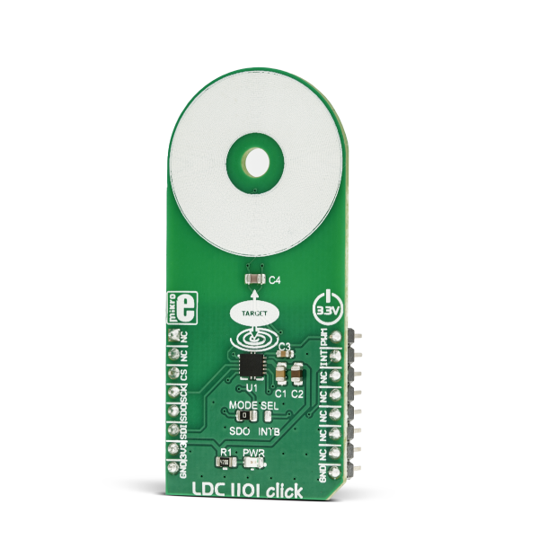
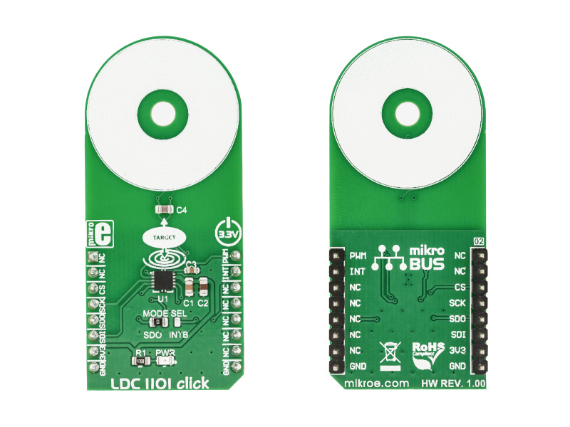
LDC1101 click is an inductance-to-digital converter Click Board. It is designed for a range of different applications, based on the inductivity measurements. You can use it to detect the position, rotation, or motion of an object. LDC1101 carries the LDC1101, the integrated, high-resolution, high-speed, inductance-to-digital converter.

No Abuse Reported

Do you want to subscribe in order to receive notifications regarding "LDC 1101 click" changes.

Do you want to unsubscribe in order to stop receiving notifications regarding "LDC 1101 click" changes.

Do you want to report abuse regarding "LDC 1101 click".

  • mikroSDK Library 2.0.0.0
  • Comments (0)
DOWNLOAD LINK RELATED COMPILER CONTAINS
mikroBasic PRO for ARM
  • lib
  • src
  • exa
  • hlp
  • hex
  • sch
  • pcb
  • doc
mikroBasic PRO for AVR
  • lib
  • src
  • exa
  • hlp
  • hex
  • sch
  • pcb
  • doc
mikroBasic PRO for dsPIC30/33 & PIC24
  • lib
  • src
  • exa
  • hlp
  • hex
  • sch
  • pcb
  • doc
mikroBasic PRO for FT90x
  • lib
  • src
  • exa
  • hlp
  • hex
  • sch
  • pcb
  • doc
mikroBasic PRO for PIC
  • lib
  • src
  • exa
  • hlp
  • hex
  • sch
  • pcb
  • doc
mikroBasic PRO for PIC32
  • lib
  • src
  • exa
  • hlp
  • hex
  • sch
  • pcb
  • doc
mikroC PRO for ARM
  • lib
  • src
  • exa
  • hlp
  • hex
  • sch
  • pcb
  • doc
mikroC PRO for AVR
  • lib
  • src
  • exa
  • hlp
  • hex
  • sch
  • pcb
  • doc
mikroC PRO for dsPIC30/33 & PIC24
  • lib
  • src
  • exa
  • hlp
  • hex
  • sch
  • pcb
  • doc
mikroC PRO for FT90x
  • lib
  • src
  • exa
  • hlp
  • hex
  • sch
  • pcb
  • doc
mikroC PRO for PIC
  • lib
  • src
  • exa
  • hlp
  • hex
  • sch
  • pcb
  • doc
mikroC PRO for PIC32
  • lib
  • src
  • exa
  • hlp
  • hex
  • sch
  • pcb
  • doc
mikroPascal PRO for ARM
  • lib
  • src
  • exa
  • hlp
  • hex
  • sch
  • pcb
  • doc
mikroPascal PRO for AVR
  • lib
  • src
  • exa
  • hlp
  • hex
  • sch
  • pcb
  • doc
mikroPascal PRO for dsPIC30/33 & PIC24
  • lib
  • src
  • exa
  • hlp
  • hex
  • sch
  • pcb
  • doc
mikroPascal PRO for FT90x
  • lib
  • src
  • exa
  • hlp
  • hex
  • sch
  • pcb
  • doc
mikroPascal PRO for PIC
  • lib
  • src
  • exa
  • hlp
  • hex
  • sch
  • pcb
  • doc
mikroPascal PRO for PIC32
  • lib
  • src
  • exa
  • hlp
  • hex
  • sch
  • pcb
  • doc

mikroSDK Library Blog

LDC 1101 click

LDC 1101 click

Native view of the LDC 1101 click board.

View full image
LDC 1101 click

LDC 1101 click

Front and back view of the LDC 1101 click board.

View full image

Library Description

The library initializes and defines the SPI bus driver and drivers that offer a choice for writing data in address and reading data from address. The library includes function for read RP data and L data. The user also has the function for initializes chip, funstion for go to RP mode or L mode, Function for set porew mode and function for read interrupt state.

Key functions:

  • uint8_t ldc1101_init() - Functions for initialization chip
  • void ldc1101_setPowerMode(uint8_t mode) - Functions for settings power mode
  • void ldc1101_goTo_RPmode() - Functions for go to RP mode
  • uint16_t ldc1101_getRPData() - Functions for reads RP data

Examples description

The application is composed of the three sections :

  • System Initialization - Initializes I2C module and sets CS pin as OUTPUT and PWM and INT pin INPUT
  • Application Initialization - Driver initialization, standard configurations and start measurement
  • Application Task - (code snippet) - Reads RP data and logs data to USBUART every 100 ms.
  • note: Example demonstrates measurement of inductance change depending on the linear motion of the metal object. Induction of the linear metal position depends on the type of metal and the configuration.
void applicationTask()
{
    RP_Data = ldc1101_getRPData();
    IntToStr(RP_Data, demoText);
    mikrobus_logWrite(" Inductive Linear Position :", _LOG_TEXT);
    mikrobus_logWrite(demoText, _LOG_LINE);
    Delay_100ms();
}

Other mikroE Libraries used in the example:

  • SPI
  • UART

Additional notes and information

Depending on the development board you are using, you may need USB UART clickUSB UART 2 click or RS232 click to connect to your PC, for development systems with no UART to USB interface available on the board. The terminal available in all MikroElektronika compilers, or any other terminal application of your choice, can be used to read the message.

ALSO FROM THIS AUTHOR

RTK Base Click

0

RTK Base Click is a compact add-on board used to improve the positional accuracy of the compatible RTK Rover board. This board features Quectel’s LG69TASMD, a dual-band multi-constellation GNSS module featuring a high-performance and high-reliability positioning engine. This module carries an RTK base station function by calculating and transmitting differential correction data via radio to allow the roving GPS to correct its position. It features the fifth generation of STMicroelectronics® positioning receiver platform with 80 tracking and four fast acquisition channels, supports up to 4 concurrent global constellations (GPS, QZSS, Galileo, and BDS) alongside RTCM 3.x protocol and commonly used UART interface.

[Learn More]

MCP251863 Click

0

MCP251863 Click is a compact add-on board representing a complete CAN solution used as a control node in a CAN network. This board features the MCP251863, IC representing a compact solution with a controller and a transceiver in one package, the MCP2518FD and ATA6563 from Microchip. The ATA6563, a low-level physical layer IC (PHY), provides a physical connection with the CAN bus itself, while the CAN controller MCP2518FD represents an interface between the MCU and the PHY. It features three operating modes with dedicated fail-safe features, remote wake-up via CAN, and ideally passive behavior when powered off on the CAN bus. This Click board™ is suitable for developing a wide range of automotive diagnostic applications, even on MCUs that don’t support CAN interface.

[Learn More]

Proximity 11 Click

0

Proximity 11 Click is a close-range proximity sensing Click board™, equipped with the RPR-0521RS, a very accurate and power-efficient proximity and ambient Light Sensor with IrLED.

[Learn More]