TOP Contributors

  1. MIKROE (2784 codes)
  2. Alcides Ramos (405 codes)
  3. Shawon Shahryiar (307 codes)
  4. jm_palomino (133 codes)
  5. Bugz Bensce (97 codes)
  6. S P (73 codes)
  7. dany (71 codes)
  8. MikroBUS.NET Team (35 codes)
  9. NART SCHINACKOW (34 codes)
  10. Armstrong Subero (27 codes)

Most Downloaded

  1. Timer Calculator (141815 times)
  2. FAT32 Library (74951 times)
  3. Network Ethernet Library (59306 times)
  4. USB Device Library (49305 times)
  5. Network WiFi Library (45102 times)
  6. FT800 Library (44668 times)
  7. GSM click (31280 times)
  8. mikroSDK (30209 times)
  9. microSD click (27656 times)
  10. PID Library (27562 times)
Libstock prefers package manager

Package Manager

We strongly encourage users to use Package manager for sharing their code on Libstock website, because it boosts your efficiency and leaves the end user with no room for error. [more info]

< Back
mikroSDK Library

SwipeSwitch click

Rating:

5

Author: MIKROE

Last Updated: 2019-05-10

Package Version: 1.0.0.0

mikroSDK Library: 1.0.0.0

Category: Capacitive

Downloaded: 2169 times

Not followed.

License: MIT license  

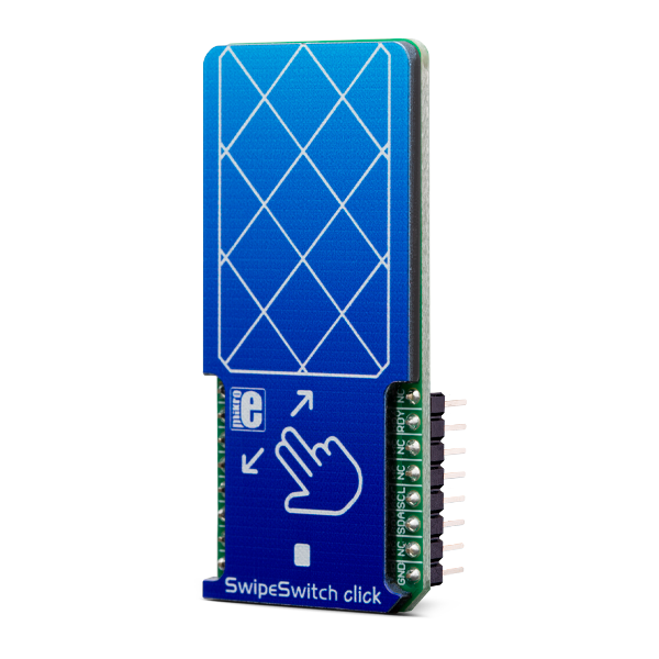
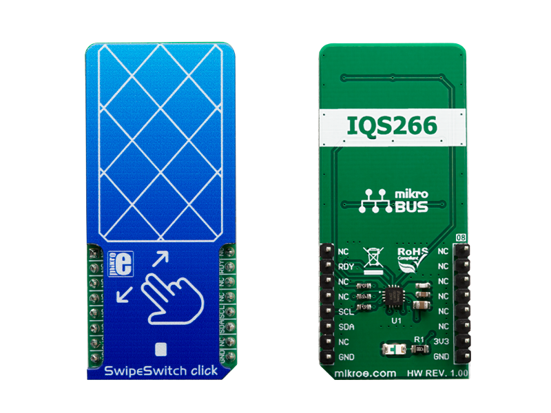
SwipeSwitch click is capacitive touch, gesture, and proximity sensing Click board, which is equipped with the IQS266, an integrated trackpad controller circuit which features ProxSense® and IQ Switch® technologies.

No Abuse Reported

Do you want to subscribe in order to receive notifications regarding "SwipeSwitch click" changes.

Do you want to unsubscribe in order to stop receiving notifications regarding "SwipeSwitch click" changes.

Do you want to report abuse regarding "SwipeSwitch click".

  • mikroSDK Library 2.0.0.0
  • Comments (0)

mikroSDK Library Blog

SwipeSwitch click

SwipeSwitch click

Native view of the SwipeSwitch click board.

View full image
SwipeSwitch click

SwipeSwitch click

Front and back view of the SwipeSwitch click board.

View full image

Library Description

This library contains all the functions required to work with SwipeSwitch click.

Key functions:

  • void swipeswitch_init() - Function for initialization chip.
  • void swipeswitch_goToEventMode() - Function for go to Event mode.
  • uint8_t swipeswitch_waitForReady() - Function for checking RDY pins.

Examples description

The application is composed of the three sections :

  • System Initialization - Initialization I2C module and sets INT pin as INPUT.
  • Application Initialization - Initialization and configuration of the chip for measurement.
  • Application Task - (code snippet) : In the first test mode, it checks whether or not a new event ocurred (TAP or SWIPE). If it did, it writes out data regarding that event via UART. In the second test mode, X and Y coordinates are being read and logged via UART.

Note: After reading data or status registers, there is a certain time which must pass until the device is ready again. The device is ready for a new conversion and reading after the Ready pin is LOW.

void applicationTask()
{
    if(displayMode == 0)
    {
        while(swipeswitch_waitForReady() != 0);
        events = swipeswitch_readEvents();
        while(swipeswitch_waitForReady() != 0);
        gestures = swipeswitch_readGestures();

        if((events & (_SWIPESWITCH_EVENT_SWIPE)) != 0 )
        {
            if((gestures & _SWIPESWITCH_GESTURE_SWIPE_UP) != 0)
            {
                mikrobus_logWrite("SWIPE UP", _LOG_LINE);
            }
            if((gestures & _SWIPESWITCH_GESTURE_SWIPE_DOWN) != 0)
            {
                mikrobus_logWrite("SWIPE DOWN", _LOG_LINE);
            }
            if((gestures & _SWIPESWITCH_GESTURE_SWIPE_LEFT) != 0)
            {
                mikrobus_logWrite("SWIPE LEFT", _LOG_LINE);
            }
            if((gestures & _SWIPESWITCH_GESTURE_SWIPE_RIGHT) != 0)
            {
                mikrobus_logWrite("SWIPE RIGHT", _LOG_LINE);
            }
        }
        else if ((events & (_SWIPESWITCH_EVENT_TAP)) != 0)
        {
            mikrobus_logWrite("TAP", _LOG_LINE);
        }
    }
    else
    {
        while(swipeswitch_waitForReady() != 0);
        xCoordinate = swipeswitch_readXCoordinate();
        while(swipeswitch_waitForReady() != 0);
        yCoordinate = swipeswitch_readYCoordinate();

        if((xCoordinate != oldXCoordinate) || (yCoordinate != oldYCoordinate))
        {
            mikrobus_logWrite("Coordinate : (", _LOG_TEXT);
            IntToStr(xCoordinate, demoText);
            mikrobus_logWrite(demoText, _LOG_TEXT);
            mikrobus_logWrite(",", _LOG_TEXT);
            IntToStr(yCoordinate, demoText);
            mikrobus_logWrite(demoText, _LOG_TEXT);
            mikrobus_logWrite(")", _LOG_LINE);
            oldXCoordinate = xCoordinate;
            oldYCoordinate = yCoordinate;
        }
    }
    Delay_ms( 300 );
}

Other mikroE Libraries used in the example:

  • I2C

Additional notes and informations

Depending on the development board you are using, you may need USB UART clickUSB UART 2 click or RS232 click to connect to your PC, for development systems with no UART to USB interface available on the board. The terminal available in all MikroElektronika compilers, or any other terminal application of your choice, can be used to read the message.

ALSO FROM THIS AUTHOR

TempHum 15 Click

0

Temp&Hum 15 Click is a compact add-on board that contains the 4th generation of best-in-class SHT humidity sensing solution from Sensirion. This board features the SHT40, a high-accuracy ultra-low-power 16-bit relative humidity, and temperature sensor.

[Learn More]

Clock Gen 6 Click

0

Clock Gen 6 Click is a compact add-on board representing a digital oscillator solution. This board features the MIC1557, an IttyBitty CMOS RC oscillator designed to provide rail-to-rail pulses for precise time delay or frequency generation from Microchip Technology. The MIC1557 has a single threshold and trigger connection, internally connected, for astable (oscillator) operation only. It also has an enable/reset control signal routed to the RST pin of the mikroBUS™ socket, which controls the bias supply to the oscillator’s internal circuitry and optimizes power consumption used for oscillator power ON/OFF purposes. In addition, it provides the ability to select the desired frequency programmed via a digital potentiometer, the MAX5401.

[Learn More]

eINK click

10

eINK click is an adapter for connecting eINK displays, with a 24pin ribbon cable. The eINK display sold with the click can retain the image even when the power is off. The click is designed to run on a 3.3V power supply.

[Learn More]