TOP Contributors

  1. MIKROE (2762 codes)
  2. Alcides Ramos (374 codes)
  3. Shawon Shahryiar (307 codes)
  4. jm_palomino (118 codes)
  5. Bugz Bensce (90 codes)
  6. S P (73 codes)
  7. dany (71 codes)
  8. MikroBUS.NET Team (35 codes)
  9. NART SCHINACKOW (34 codes)
  10. Armstrong Subero (27 codes)

Most Downloaded

  1. Timer Calculator (139251 times)
  2. FAT32 Library (71748 times)
  3. Network Ethernet Library (57120 times)
  4. USB Device Library (47430 times)
  5. Network WiFi Library (43082 times)
  6. FT800 Library (42403 times)
  7. GSM click (29835 times)
  8. mikroSDK (28077 times)
  9. PID Library (26885 times)
  10. microSD click (26198 times)
Libstock prefers package manager

Package Manager

We strongly encourage users to use Package manager for sharing their code on Libstock website, because it boosts your efficiency and leaves the end user with no room for error. [more info]

< Back
mikroSDK Library

IR Grid 2 click

Rating:

5

Author: MIKROE

Last Updated: 2018-10-22

Package Version: 1.0.0.0

mikroSDK Library: 1.0.0.0

Category: Optical

Downloaded: 2496 times

Not followed.

License: MIT license  

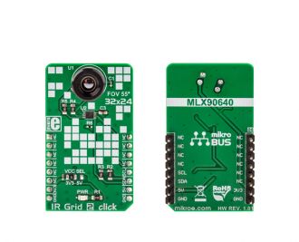
IR Grid 2 click is a thermal imaging sensor. It has an array of 768 very sensitive factory calibrated IR elements (pixels), arranged in 32 rows of 24 pixels.

No Abuse Reported

Do you want to subscribe in order to receive notifications regarding "IR Grid 2 click" changes.

Do you want to unsubscribe in order to stop receiving notifications regarding "IR Grid 2 click" changes.

Do you want to report abuse regarding "IR Grid 2 click".
  • mikroSDK Library 2.0.0.0
  • Comments (0)

mikroSDK Library Blog

IR Grid 2 click

IR Grid 2 click

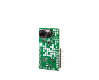
Native view of the IR Grid 2 click board.

View full image
IR Grid 2 click

IR Grid 2 click

Front and back view of the IR Grid 2 click board.

View full image

Library Description

The library contains all the necessary functions for successful work with IR Grid 2 click.

Key functions :

  • void irgrid2_init() - Functions for initialization chip
  • void irgrid2_getPixelTemperature(float *Ta, float *pixelTemp) - Functions for reads Ambient temperature and pixel temperature

Example description

The application is composed of three sections :

  • System Initialization - Initializes I2C module and USB UART for data logging
  • Application Initialization - Initializes driver init and IR Grid 2 module
  • Application Task - (code snippet) - Reads the temperature of all pixels and creates a pixel temperature matrix that logs on usbuart every 500ms
  • note : The sensor needs about 4 minutes for calibration
void applicationTask()
{
 irgrid2_getPixelTemperature(&Ta,&pixelTemp[0]);

 mikrobus_logWrite("Ambient temperature: ",_LOG_TEXT);
 FloatToStr(Ta,demoText);
 mikrobus_logWrite(demoText,_LOG_LINE);
 mikrobus_logWrite(" ", _LOG_LINE);
 mikrobus_logWrite("--- Pixel temperature matrix 32x24 ---", _LOG_LINE);

 for ( cnt = 0 ; cnt < 768 ; cnt++)
 {
 FloatToStr(pixelTemp[cnt],demoText);
 demoText[ 5 ] = 0 ;
 mikrobus_logWrite(demoText, _LOG_TEXT);
 mikrobus_logWrite("|", _LOG_TEXT);
 Delay_1ms();
 if(((cnt % 32) == 0) && (cnt > 0))
 {
 mikrobus_logWrite(" ", _LOG_LINE);
 }
 }
 mikrobus_logWrite(" ", _LOG_LINE);
 Delay_ms( 500 );
}


Other mikroE Libraries used in the example:

  • I2C

Additional notes and information

Depending on the development board you are using, you may need USB UART clickUSB UART 2 click or RS232 click to connect to your PC, for development systems with no UART to USB interface available on the board. The terminal available in all MikroElektronika compilers, or any other terminal application of your choice, can be used to read the message.

ALSO FROM THIS AUTHOR

DIGI POT 9 Click

0

DIGI POT 9 Click is a compact add-on board used as a digitally controlled potentiometer. This board features the AD5235, a dual-channel, nonvolatile memory, digitally controlled potentiometer from Analog Devices. The AD5235's versatile programming via an SPI-compatible serial interface allows multiple modes of operation and adjustment. The resistor wiper position is determined by the RDAC register contents, which act as a scratchpad register, allowing unlimited changes of resistance settings. The nominal resistance of the RDAC between terminal A and terminal B (RAB) is 250 kΩ with 1024 positions (10-bit resolution).

[Learn More]

TFT Proto 4.3in - Example

1

TFT Proto 4.3in carries a 480x272 ATO43B35 TFT screen covered with a 4-wire resistive touchscreen panel. To drive the 262k-color display, there's an SSD1963 graphic controller. The touchpanel is driven by an advanced STMPE811 controller. Source code examples demonstrate calculator on TFT display.

[Learn More]

Oximeter 5 Click

0

Oximeter 5 Click is a compact add-on board suitable for measuring blood oxygen saturation. This board features the MAX30102, integrated pulse oximetry, and heart-rate monitor module from Analog Devices. The MAX30102 includes internal LEDs, photodetectors, optical elements, and low-noise electronics with ambient light rejection. It operates on a single 1.8V power supply acquired from both mikroBUS™ power rails for the internal LEDs, communicating through a standard I2C compatible interface. The MAX30102 can be shut down through software with zero standby current, allowing the power rails to remain powered at all times.

[Learn More]