TOP Contributors

  1. MIKROE (2784 codes)
  2. Alcides Ramos (405 codes)
  3. Shawon Shahryiar (307 codes)
  4. jm_palomino (133 codes)
  5. Bugz Bensce (97 codes)
  6. S P (73 codes)
  7. dany (71 codes)
  8. MikroBUS.NET Team (35 codes)
  9. NART SCHINACKOW (34 codes)
  10. Armstrong Subero (27 codes)

Most Downloaded

  1. Timer Calculator (141237 times)
  2. FAT32 Library (74038 times)
  3. Network Ethernet Library (58662 times)
  4. USB Device Library (48767 times)
  5. Network WiFi Library (44489 times)
  6. FT800 Library (44034 times)
  7. GSM click (30784 times)
  8. mikroSDK (29607 times)
  9. PID Library (27342 times)
  10. microSD click (27223 times)
Libstock prefers package manager

Package Manager

We strongly encourage users to use Package manager for sharing their code on Libstock website, because it boosts your efficiency and leaves the end user with no room for error. [more info]

< Back
mikroSDK Library

L meter click

Rating:

5

Author: MIKROE

Last Updated: 2019-06-28

Package Version: 1.0.0.0

mikroSDK Library: 1.0.0.0

Category: Measurements

Downloaded: 3933 times

Not followed.

License: MIT license  

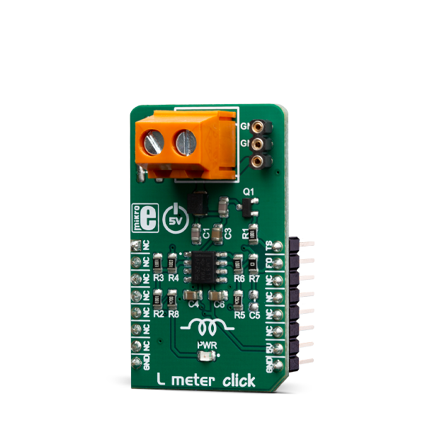
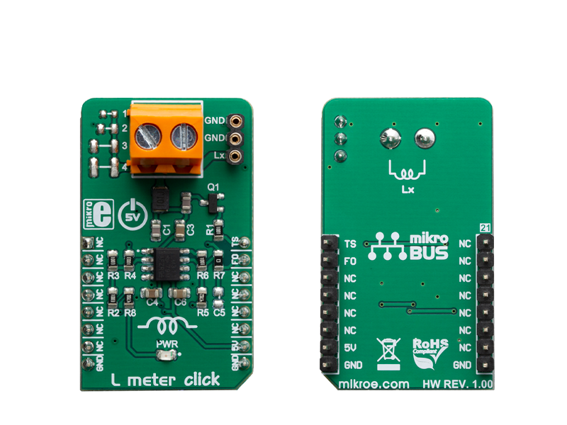
L Meter Click is a compact and accurate Click board, capable of measuring and monitoring the inductance of the external component.

No Abuse Reported

Do you want to subscribe in order to receive notifications regarding "L meter click" changes.

Do you want to unsubscribe in order to stop receiving notifications regarding "L meter click" changes.

Do you want to report abuse regarding "L meter click".

  • Information
  • Comments (0)
DOWNLOAD LINK RELATED COMPILER CONTAINS
mikroBasic PRO for ARM
  • lib
  • src
  • exa
  • hlp
  • hex
  • sch
  • pcb
  • doc
mikroBasic PRO for AVR
  • lib
  • src
  • exa
  • hlp
  • hex
  • sch
  • pcb
  • doc
mikroBasic PRO for dsPIC30/33 & PIC24
  • lib
  • src
  • exa
  • hlp
  • hex
  • sch
  • pcb
  • doc
mikroBasic PRO for FT90x
  • lib
  • src
  • exa
  • hlp
  • hex
  • sch
  • pcb
  • doc
mikroBasic PRO for PIC
  • lib
  • src
  • exa
  • hlp
  • hex
  • sch
  • pcb
  • doc
mikroBasic PRO for PIC32
  • lib
  • src
  • exa
  • hlp
  • hex
  • sch
  • pcb
  • doc
mikroC PRO for ARM
  • lib
  • src
  • exa
  • hlp
  • hex
  • sch
  • pcb
  • doc
mikroC PRO for AVR
  • lib
  • src
  • exa
  • hlp
  • hex
  • sch
  • pcb
  • doc
mikroC PRO for dsPIC30/33 & PIC24
  • lib
  • src
  • exa
  • hlp
  • hex
  • sch
  • pcb
  • doc
mikroC PRO for FT90x
  • lib
  • src
  • exa
  • hlp
  • hex
  • sch
  • pcb
  • doc
mikroC PRO for PIC
  • lib
  • src
  • exa
  • hlp
  • hex
  • sch
  • pcb
  • doc
mikroC PRO for PIC32
  • lib
  • src
  • exa
  • hlp
  • hex
  • sch
  • pcb
  • doc
mikroPascal PRO for ARM
  • lib
  • src
  • exa
  • hlp
  • hex
  • sch
  • pcb
  • doc
mikroPascal PRO for AVR
  • lib
  • src
  • exa
  • hlp
  • hex
  • sch
  • pcb
  • doc
mikroPascal PRO for dsPIC30/33 & PIC24
  • lib
  • src
  • exa
  • hlp
  • hex
  • sch
  • pcb
  • doc
mikroPascal PRO for FT90x
  • lib
  • src
  • exa
  • hlp
  • hex
  • sch
  • pcb
  • doc
mikroPascal PRO for PIC
  • lib
  • src
  • exa
  • hlp
  • hex
  • sch
  • pcb
  • doc
mikroPascal PRO for PIC32
  • lib
  • src
  • exa
  • hlp
  • hex
  • sch
  • pcb
  • doc

mikroSDK Library Blog

L Meter click

L Meter click

Native view of the L Meter click board.

View full image
L Meter click

L Meter click

Front and back view of the L Meter click board.

View full image

Library Description

Library contains all the necessary functions for successfully reading Frequency and Inductance on the indicator.

Key functions:

  • uint32_t lmeter_getFrequency() - Frequency reading function.
  • float lmeter_getCoilInductance() - Inductances reading function.
  • void lmeter_tick() - Timer Tick functions.

Examples description

The application is composed of the three sections :

  • System Initialization - Sets PWM pin as OUTPUT and INT pin as INPUT.
  • Application Initialization - Initialization driver init and Timer init.
  • Application Task - Reads the frequency and induction on the inductor in [uH] and this data logs to USBUART. - Waits for valid user input and executes functions based on set of valid commands.
  • Commands :
    'F' - For calculating and logging frequencies
    'L' - For calculating and logging inductances
    'T' - Enabling and disabling additional C2 capacitors
void applicationTask()
{
    uint8_t dataReady_;
    char receivedData_;

    dataReady_ = UART_Rdy_Ptr( );

    if (dataReady_ != 0)
    {
        receivedData_ = UART_Rd_Ptr( );

        switch (receivedData_)
        {
            case 'F' :
            {
                mikrobus_logWrite(" --- PLEASE WAIT FOR THE CALCULATION PROCESS TO COMPLETE ---", _LOG_LINE);
                lmeter_setTimer();
                _Frequency = lmeter_getFrequency();
                if (_Frequency < _LMETER_MIN_INDUCTANCE_RANGE)
                {
                    mikrobus_logWrite(" Frequency is out of range !!! ", _LOG_LINE);
                    mikrobus_logWrite("  ", _LOG_LINE);
                }
                else
                {
                    FloatToStr(_Frequency, demoText);
                    mikrobus_logWrite(" Frequency = ", _LOG_TEXT);
                    mikrobus_logWrite(demoText, _LOG_TEXT);
                    mikrobus_logWrite(" kHz ", _LOG_LINE);
                    mikrobus_logWrite("  ", _LOG_LINE);
                }
                break;
            }
            case 'L' :
            {
                mikrobus_logWrite(" --- PLEASE WAIT FOR THE CALCULATION PROCESS TO COMPLETE ---", _LOG_LINE);
                lmeter_setTimer();
                _Frequency = lmeter_getFrequency();
                
                if (_Frequency < _LMETER_MIN_INDUCTANCE_RANGE)
                {
                    mikrobus_logWrite(" Frequency is out of range !!! ", _LOG_LINE);
                    mikrobus_logWrite("  ", _LOG_LINE);
                }
                else
                {
                    _Inductance = lmeter_getCoilInductance(_Frequency);

                    FloatToStr(_Inductance, demoText);
                    mikrobus_logWrite(" Inductance = ", _LOG_TEXT);
                    mikrobus_logWrite(demoText, _LOG_TEXT);
                    mikrobus_logWrite(" uH ", _LOG_LINE);
                    mikrobus_logWrite("  ", _LOG_LINE);
                }
                break;
            }
            case 'T' :
            {
                if (T_SW == _LMETER_T_SW_ENABLE)
                {
                    T_SW = _LMETER_T_SW_DISABLE;
                    lmeter_setTSpin( _LMETER_T_SW_DISABLE );
                    mikrobus_logWrite(" ---  NEW SETTINGS - DISABLE [C2] CAPACITOR --- ", _LOG_LINE);
                    mikrobus_logWrite("* The sum of all the capacitors is 1000pF ", _LOG_LINE);
                    mikrobus_logWrite("* Disabled capacitor [C2]", _LOG_LINE);
                }
                else
                {
                    T_SW = _LMETER_T_SW_ENABLE;
                    lmeter_setTSpin( _LMETER_T_SW_ENABLE );
                    mikrobus_logWrite(" ---  NEW SETTINGS - ENABLE [C2] CAPACITOR --- ", _LOG_LINE);
                    mikrobus_logWrite("* The sum of all the capacitors is 500pF ", _LOG_LINE);
                    mikrobus_logWrite("* Active new capacitor [C2]", _LOG_LINE);
                }
                break;
            }
        }
    }
}

Other mikroE Libraries used in the example:

  • Conversions Library

Additional notes and informations

Depending on the development board you are using, you may need USB UART clickUSB UART 2 click or RS232 click to connect to your PC, for development systems with no UART to USB interface available on the board. The terminal available in all MikroElektronika compilers, or any other terminal application of your choice, can be used to read the message.

ALSO FROM THIS AUTHOR

RS232 2 Click

0

The RS232 communication standard is established back in the ‘60s, but thanks to its implementation on a wide range of devices.

[Learn More]

Multi Stepper TB62269 Click

0

Multi Stepper Click is a compact add-on board that contains a bipolar stepper motor driver. This board features the TB62269FTG, PWM method CLOCK-in controlled bipolar stepping motor driver from Toshiba Semiconductor. It supports a PWM constant-current control drive and allows from full-step up to 1/32 steps resolution for less motor noise and smoother control. It has a wide operating voltage range of 10V to 38V with an output current capacity of 1.2A in addition to several built-in error detection circuits.

[Learn More]

N-PLC Click

0

N-PLC Click is a compact add-on board that uses existing electrical power lines to transmit data signals. This board features the SM2400, an advanced multi-standard Narrow-band Power Line Communication (N-PLC) modem from Semitech. The SM2400 features a dual-core architecture, a DSP core for N-PLC modulations, and a 32-bit core for running protocols for superior communication performance and flexibility for various open standards and customized implementations. It includes firmware options for IEEE 1901.2 compliant PHY and MAC layers, a 6LoWPAN data link layer, and special modes for industrial IoT applications. In addition to the ability to accept signals from another PLC modem or the power line communication AC coupling circuit, this board also has a handful of other features, such as a selectable interface and power supply, firmware update capabilities, LED indicators, and many others.

[Learn More]