TOP Contributors

  1. MIKROE (2784 codes)
  2. Alcides Ramos (405 codes)
  3. Shawon Shahryiar (307 codes)
  4. jm_palomino (133 codes)
  5. Bugz Bensce (97 codes)
  6. S P (73 codes)
  7. dany (71 codes)
  8. MikroBUS.NET Team (35 codes)
  9. NART SCHINACKOW (34 codes)
  10. Armstrong Subero (27 codes)

Most Downloaded

  1. Timer Calculator (141803 times)
  2. FAT32 Library (74940 times)
  3. Network Ethernet Library (59303 times)
  4. USB Device Library (49298 times)
  5. Network WiFi Library (45094 times)
  6. FT800 Library (44656 times)
  7. GSM click (31275 times)
  8. mikroSDK (30205 times)
  9. microSD click (27654 times)
  10. PID Library (27561 times)
Libstock prefers package manager

Package Manager

We strongly encourage users to use Package manager for sharing their code on Libstock website, because it boosts your efficiency and leaves the end user with no room for error. [more info]

< Back
mikroSDK Library

IR Grid 3 click

Rating:

5

Author: MIKROE

Last Updated: 2018-11-05

Package Version: 1.0.0.0

mikroSDK Library: 1.0.0.0

Category: Optical

Downloaded: 2837 times

Not followed.

License: MIT license  

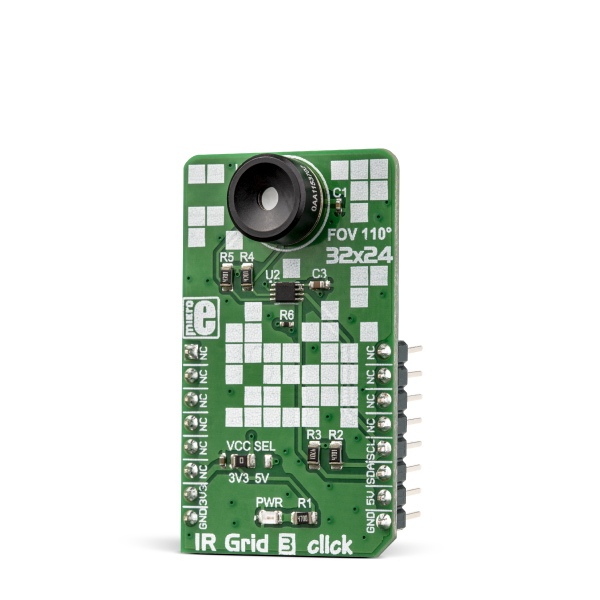
IR Grid 3 click is a thermal imaging sensor. It has an array of 768 very sensitive, factory calibrated IR elements (pixels), arranged in 32 rows of 24 pixels, each measuring an object temperature up to 300ËšC within its local Field of View (FOV).

No Abuse Reported

Do you want to subscribe in order to receive notifications regarding "IR Grid 3 click" changes.

Do you want to unsubscribe in order to stop receiving notifications regarding "IR Grid 3 click" changes.

Do you want to report abuse regarding "IR Grid 3 click".

  • mikroSDK Library 2.0.0.0
  • Comments (0)

mikroSDK Library Blog

IR Grid 3 click

IR Grid 3 click

Native view of the IR Grid 3 Click board.

View full image
IR Grid 3 click

IR Grid 3 click

Front and back view of the IR Grid 3 Click board.

View full image

Library Description

The library contains all the necessary functions for successful work with IR Grid 3 Click board.

Key functions:

  • void irgrid3_deviceConfiguration() - Functions for device configuration
  • void irgrid3_getPixelTemperature(float *Ta, float *pixelTemp) - Functions for reads Ambient temperature and pixel temperature

Examples description

The application is composed of the three sections :

  • System Initialization - Initializes I2C module and USB UART for data logging
  • Application Initialization - Initializes driver init and IR Grid 3 module
  • Application Task - (code snippet) - Reads the temperature of all pixels and creates a pixel temperature matrix that logs on usbuart every 500ms
void applicationTask()
{
	
 
	 irgrid3_getPixelTemperature(&Ta,&pixelTemp[0]);

    mikrobus_logWrite("Ambient temperature:  ",_LOG_TEXT);
    FloatToStr(Ta,demoText);
    mikrobus_logWrite(demoText,_LOG_LINE);
    mikrobus_logWrite(" ", _LOG_LINE);
    mikrobus_logWrite("--- Pixel temperature matrix 32x24 ---", _LOG_LINE);


    for ( cnt = 0 ; cnt < 768 ; cnt++)
    {
        FloatToStr(pixelTemp[cnt],demoText);
        demoText[ 5 ] = 0 ;
        mikrobus_logWrite(demoText, _LOG_TEXT);
        mikrobus_logWrite("|", _LOG_TEXT);
        Delay_1ms();
        if(((cnt % 32) == 0) && (cnt > 0))
        {
            mikrobus_logWrite(" ", _LOG_LINE);
        }
    }
    mikrobus_logWrite(" ", _LOG_LINE);
    Delay_ms( 500 );

	}

Note: The sensor needs about 4 minutes for calibration.

Other mikroE Libraries used in the example:

    • I2C

Additional notes and information

Depending on the development board you are using, you may need USB UART clickUSB UART 2 click or RS232 click to connect to your PC, for development systems with no UART to USB interface available on the board. The terminal available in all MikroElektronika compilers, or any other terminal application of your choice, can be used to read the message.

ALSO FROM THIS AUTHOR

8x8 Y click

5

8x8 clicks are 8x8 LED matrix displays in form of add-on boards in mikroBUS form factor. Boards feature MAX7219 8-digit LED display driver module as well as 64 LED diodes.

[Learn More]

SPI Isolator 5 Click

0

SPI Isolator 5 Click is a compact add-on board with a digital isolator optimized for a serial peripheral interface. This board features the DCL541A01, a high-speed quad-channel digital isolator from Toshiba Semiconductor. Outstanding performance characteristics of the DCL541A01 are achieved by Toshiba CMOS technology and the magnetic coupling structure. In addition, they comply with UL 1577 safety-related certification, have a withstand voltage rating of 5kVrms, and operate with the external supply voltage ranging from 2.25V to 5.5V, providing compatibility with lower voltage systems enabling voltage translation functionality across the isolation barrier.

[Learn More]

V to Hz Click

0

V to HZ Click is a device that converts an analog voltage input signal into a pulse wave signal of a certain frequency. It has a linear response, so applying a voltage in a range of 0 to 5V on its input, will result in generating the pulse train with frequency linearly proportional to the input voltage.

[Learn More]