TOP Contributors

  1. MIKROE (2784 codes)
  2. Alcides Ramos (405 codes)
  3. Shawon Shahryiar (307 codes)
  4. jm_palomino (133 codes)
  5. Bugz Bensce (97 codes)
  6. S P (73 codes)
  7. dany (71 codes)
  8. MikroBUS.NET Team (35 codes)
  9. NART SCHINACKOW (34 codes)
  10. Armstrong Subero (27 codes)

Most Downloaded

  1. Timer Calculator (141292 times)
  2. FAT32 Library (74089 times)
  3. Network Ethernet Library (58715 times)
  4. USB Device Library (48826 times)
  5. Network WiFi Library (44525 times)
  6. FT800 Library (44074 times)
  7. GSM click (30805 times)
  8. mikroSDK (29659 times)
  9. PID Library (27355 times)
  10. microSD click (27251 times)
Libstock prefers package manager

Package Manager

We strongly encourage users to use Package manager for sharing their code on Libstock website, because it boosts your efficiency and leaves the end user with no room for error. [more info]

< Back
mikroSDK Library

FAN 4 click

Rating:

5

Author: MIKROE

Last Updated: 2018-10-19

Package Version: 1.0.0.0

mikroSDK Library: 1.0.0.0

Category: Brushless

Downloaded: 5017 times

Not followed.

License: MIT license  

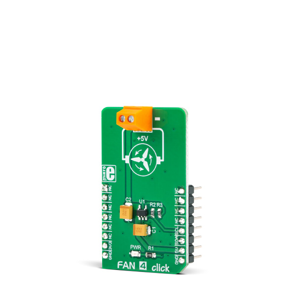
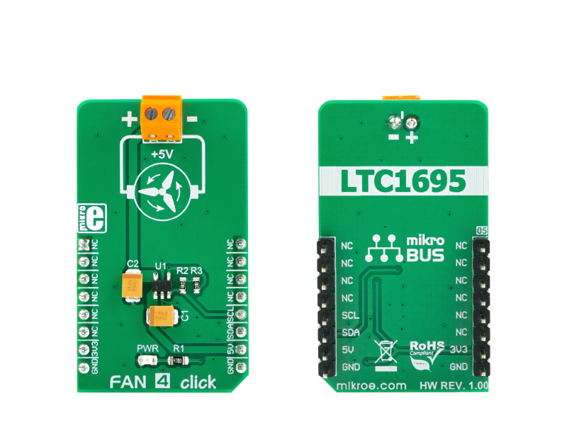
Fan 4 click is a very compact, two-wire fan driver. It utilizes an integrated 5V, DC, brushless-motor driver chip. Its output voltage regulation and current limiting capabilities allow the speed control for the two-wire DC brushless motors.

No Abuse Reported

Do you want to subscribe in order to receive notifications regarding "FAN 4 click" changes.

Do you want to unsubscribe in order to stop receiving notifications regarding "FAN 4 click" changes.

Do you want to report abuse regarding "FAN 4 click".

  • mikroSDK Library 2.0.0.0
  • Comments (0)
DOWNLOAD LINK RELATED COMPILER CONTAINS
mikroBasic PRO for ARM
  • lib
  • src
  • exa
  • hlp
  • hex
  • sch
  • pcb
  • doc
mikroBasic PRO for AVR
  • lib
  • src
  • exa
  • hlp
  • hex
  • sch
  • pcb
  • doc
mikroBasic PRO for dsPIC30/33 & PIC24
  • lib
  • src
  • exa
  • hlp
  • hex
  • sch
  • pcb
  • doc
mikroBasic PRO for FT90x
  • lib
  • src
  • exa
  • hlp
  • hex
  • sch
  • pcb
  • doc
mikroBasic PRO for PIC
  • lib
  • src
  • exa
  • hlp
  • hex
  • sch
  • pcb
  • doc
mikroBasic PRO for PIC32
  • lib
  • src
  • exa
  • hlp
  • hex
  • sch
  • pcb
  • doc
mikroC PRO for ARM
  • lib
  • src
  • exa
  • hlp
  • hex
  • sch
  • pcb
  • doc
mikroC PRO for AVR
  • lib
  • src
  • exa
  • hlp
  • hex
  • sch
  • pcb
  • doc
mikroC PRO for dsPIC30/33 & PIC24
  • lib
  • src
  • exa
  • hlp
  • hex
  • sch
  • pcb
  • doc
mikroC PRO for FT90x
  • lib
  • src
  • exa
  • hlp
  • hex
  • sch
  • pcb
  • doc
mikroC PRO for PIC
  • lib
  • src
  • exa
  • hlp
  • hex
  • sch
  • pcb
  • doc
mikroC PRO for PIC32
  • lib
  • src
  • exa
  • hlp
  • hex
  • sch
  • pcb
  • doc
mikroPascal PRO for ARM
  • lib
  • src
  • exa
  • hlp
  • hex
  • sch
  • pcb
  • doc
mikroPascal PRO for AVR
  • lib
  • src
  • exa
  • hlp
  • hex
  • sch
  • pcb
  • doc
mikroPascal PRO for dsPIC30/33 & PIC24
  • lib
  • src
  • exa
  • hlp
  • hex
  • sch
  • pcb
  • doc
mikroPascal PRO for FT90x
  • lib
  • src
  • exa
  • hlp
  • hex
  • sch
  • pcb
  • doc
mikroPascal PRO for PIC
  • lib
  • src
  • exa
  • hlp
  • hex
  • sch
  • pcb
  • doc
mikroPascal PRO for PIC32
  • lib
  • src
  • exa
  • hlp
  • hex
  • sch
  • pcb
  • doc

mikroSDK Library Blog

FAN 4 click

FAN 4 click

Native view of the FAN 4 Click board.

View full image
FAN 4 click

FAN 4 click

Front and back view of the FAN 4 Click board.

View full image

Library Description

The library performs communication with the Fan 4 Click board. The library can send command with the desired output voltage value to the DAC and can receive report from the DAC to check fault conditions. For more details check documentation.

Key functions:

  • T_FAN4_RETVAL fan4_setOutput( uint16_t outputVolt, uint8_t boostStartTimer )  - Function sets the output voltage on the desired value and turns on/off Boost Start Timer.
  • T_FAN4_RETVAL fan4_checkDiagnostic( void ) - Function checks is Thermal Shutdown or Overcurrent Fault happening and returns a diagnostic state.

Examples description

The application is composed of three sections :

  • System Initialization - Initializes peripherals and pins.
  • Application Initialization - Initializes I2C interface and puts the DAC voltage value to 0V.
  • Application Task - (code snippet) - Checks the uart command (command symbol) and performs the desired command. Possible commands are incrementing and decrementing voltage by desired step, setting the step value, setting the output voltage on minimum and maximum value. To check all commands take look on legend (L).
void applicationTask()
{
 if (UART_Rdy_Ptr())
 {
 rxDat = UART_Rd_Ptr();

 switch (rxDat)
 {
 case '1' :
 {
 stepVal = _FAN4_DAC_LSB;
 mikrobus_logWrite( "Voltage step is 78mV", _LOG_LINE );
 break;
 }
 case '2' :
 {
 stepVal = _FAN4_DAC_LSB * 2;
 mikrobus_logWrite( "Voltage step is 156mV", _LOG_LINE );
 break;
 }
 case '3' :
 {
 stepVal = _FAN4_DAC_LSB * 3;
 mikrobus_logWrite( "Voltage step is 234mV", _LOG_LINE );
 break;
 }
 case '+' :
 {
 if (voltage <= (_FAN4_MAX_VOLT_SCALE - stepVal))
 {
 voltage += stepVal;
 writeVoltage();
 fan4_setOutput( voltage, _FAN4_BOOST_START_TIMER_DIS );
 }
 else
 {
 mikrobus_logWrite( "Voltage can't be incremented", _LOG_LINE );
 }
 break;
 }
 case '-' :
 {
 if (voltage >= stepVal)
 {
 voltage -= stepVal;
 writeVoltage();
 fan4_setOutput( voltage, _FAN4_BOOST_START_TIMER_DIS );
 }
 else
 {
 mikrobus_logWrite( "Voltage can't be decremented", _LOG_LINE );
 }
 break;
 }
 case '9' :
 {
 if (voltage != _FAN4_MAX_VOLT_SCALE)
 {
 voltage = _FAN4_MAX_VOLT_SCALE;
 mikrobus_logWrite( "Voltage is 4922mV", _LOG_LINE );
 fan4_setOutput( voltage, _FAN4_BOOST_START_TIMER_DIS );
 }
 else
 {
 mikrobus_logWrite( "Voltage is already set on maximum value", _LOG_LINE );
 }
 break;
 }
 case '0' :
 {
 if (voltage != _FAN4_MIN_VOLT_SCALE)
 {
 voltage = _FAN4_MIN_VOLT_SCALE;
 mikrobus_logWrite( "Voltage is 0mV", _LOG_LINE );
 fan4_setOutput( voltage, _FAN4_BOOST_START_TIMER_DIS );
 }
 else
 {
 mikrobus_logWrite( "Voltage is already set on minimum value", _LOG_LINE );
 }
 break;
 }
 case 'L' :
 {
 writeLegend();
 break;
 }
 default :
 {
 break;
 }
 }
 }

 responseCheck = fan4_checkDiagnostic();
 checkResponse();
}

Additional Functions :

  • checkResponse - Checks a response from driver functions and shows results on uart.
  • writeLegend - Writes all possible commands on uart.
  • writeVoltage - Writes current voltage value on uart.


Other mikroE Libraries used in the example:

  • Conversions
  • I2C
  • UART

Additional notes and information

Depending on the development board you are using, you may need USB UART clickUSB UART 2 click or RS232 click to connect to your PC, for development systems with no UART to USB interface available on the board. The terminal available in all MikroElektronika compilers, or any other terminal application of your choice, can be used to read the message.

ALSO FROM THIS AUTHOR

Timer click

1

Timer click is a mikroBUS add-on board with Maxim’s DS1682 total elapsed time recorder. It holds an elapsed time counter (ETC) in conjunction with the ALARM pin. The alarm flag is one time programmable. The board communicates through I2C interface, with two additional pins: ALARM and EVENT. It uses either a 3.3V or a 5V power supply only.

[Learn More]

Ambient 4 click

5

Ambient 4 click is a light, intensity-sensing and measuring Click boardâ„¢, which features an accurate, light-intensity sensor labeled as BH1721FVC, made by ROHM corporation.

[Learn More]

Thermo 7 click - Cloud demo

5

- The example contains all the necessary initializations and settings for a G2C click on a successful connection by Click Cloud. - Thermo 7 click reads ambient temperature and the temperature value is sent to the cloud by reference THERMO7_T every 1500ms.

[Learn More]