TOP Contributors

  1. MIKROE (2650 codes)
  2. Alcides Ramos (350 codes)
  3. Shawon Shahryiar (307 codes)
  4. jm_palomino (112 codes)
  5. Chisanga Mumba (90 codes)
  6. S P (73 codes)
  7. dany (71 codes)
  8. MikroBUS.NET Team (35 codes)
  9. NART SCHINACKOW (34 codes)
  10. Armstrong Subero (27 codes)

Most Downloaded

  1. Timer Calculator (136553 times)
  2. FAT32 Library (69756 times)
  3. Network Ethernet Library (55855 times)
  4. USB Device Library (46195 times)
  5. Network WiFi Library (41816 times)
  6. FT800 Library (41009 times)
  7. GSM click (28931 times)
  8. PID Library (26386 times)
  9. mikroSDK (26297 times)
  10. microSD click (25304 times)
Libstock prefers package manager

Package Manager

We strongly encourage users to use Package manager for sharing their code on Libstock website, because it boosts your efficiency and leaves the end user with no room for error. [more info]

< Back
mikroSDK Library

Pedometer 3 click

Rating:

6

Author: MIKROE

Last Updated: 2018-12-10

Package Version: 1.0.0.0

mikroSDK Library: 1.0.0.0

Category: Motion

Downloaded: 3480 times

Not followed.

License: MIT license  

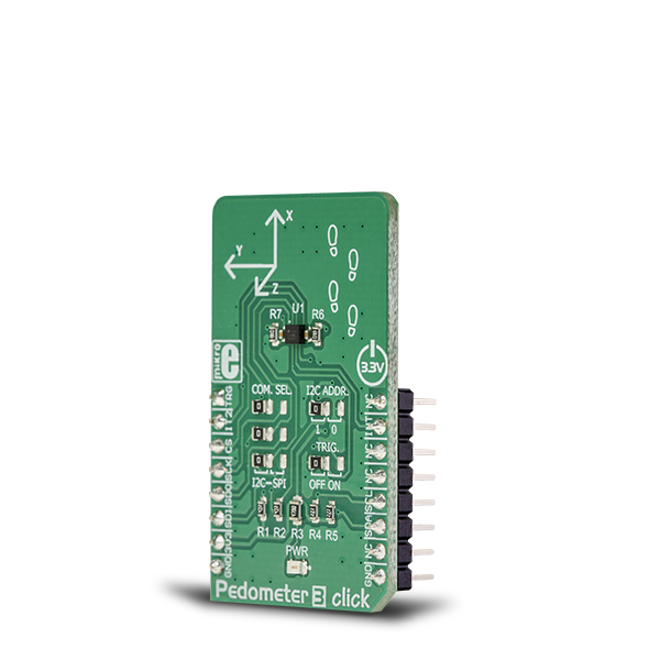
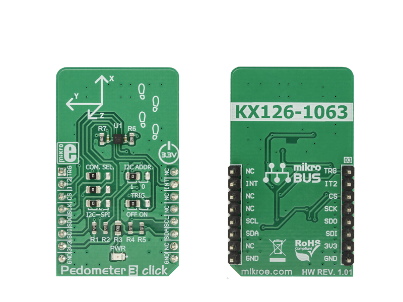
Pedometer 3 click is a three-axis acceleration sensing Click board which utilizes the KX126-1063. An advanced tri-axis acceleration sensor, KX126-1063 includes the pedometer algorithm support.

No Abuse Reported

Do you want to subscribe in order to receive notifications regarding "Pedometer 3 click" changes.

Do you want to unsubscribe in order to stop receiving notifications regarding "Pedometer 3 click" changes.

Do you want to report abuse regarding "Pedometer 3 click".

  • mikroSDK Library 2.0.0.0
  • Comments (0)
DOWNLOAD LINK RELATED COMPILER CONTAINS
mikroBasic PRO for ARM
  • lib
  • src
  • exa
  • hlp
  • hex
  • sch
  • pcb
  • doc
mikroBasic PRO for AVR
  • lib
  • src
  • exa
  • hlp
  • hex
  • sch
  • pcb
  • doc
mikroBasic PRO for dsPIC30/33 & PIC24
  • lib
  • src
  • exa
  • hlp
  • hex
  • sch
  • pcb
  • doc
mikroBasic PRO for FT90x
  • lib
  • src
  • exa
  • hlp
  • hex
  • sch
  • pcb
  • doc
mikroBasic PRO for PIC
  • lib
  • src
  • exa
  • hlp
  • hex
  • sch
  • pcb
  • doc
mikroBasic PRO for PIC32
  • lib
  • src
  • exa
  • hlp
  • hex
  • sch
  • pcb
  • doc
mikroC PRO for ARM
  • lib
  • src
  • exa
  • hlp
  • hex
  • sch
  • pcb
  • doc
mikroC PRO for AVR
  • lib
  • src
  • exa
  • hlp
  • hex
  • sch
  • pcb
  • doc
mikroC PRO for dsPIC30/33 & PIC24
  • lib
  • src
  • exa
  • hlp
  • hex
  • sch
  • pcb
  • doc
mikroC PRO for FT90x
  • lib
  • src
  • exa
  • hlp
  • hex
  • sch
  • pcb
  • doc
mikroC PRO for PIC
  • lib
  • src
  • exa
  • hlp
  • hex
  • sch
  • pcb
  • doc
mikroC PRO for PIC32
  • lib
  • src
  • exa
  • hlp
  • hex
  • sch
  • pcb
  • doc
mikroPascal PRO for ARM
  • lib
  • src
  • exa
  • hlp
  • hex
  • sch
  • pcb
  • doc
mikroPascal PRO for AVR
  • lib
  • src
  • exa
  • hlp
  • hex
  • sch
  • pcb
  • doc
mikroPascal PRO for dsPIC30/33 & PIC24
  • lib
  • src
  • exa
  • hlp
  • hex
  • sch
  • pcb
  • doc
mikroPascal PRO for FT90x
  • lib
  • src
  • exa
  • hlp
  • hex
  • sch
  • pcb
  • doc
mikroPascal PRO for PIC
  • lib
  • src
  • exa
  • hlp
  • hex
  • sch
  • pcb
  • doc
mikroPascal PRO for PIC32
  • lib
  • src
  • exa
  • hlp
  • hex
  • sch
  • pcb
  • doc

mikroSDK Library Blog

Pedometer 3 click

Pedometer 3 click

Native view of the Pedometer 3 click board.

View full image
Pedometer 3 click

Pedometer 3 click

Front and back view of the Pedometer 3 click board.

View full image

Library Description

The library initializes and defines the I2C or SPI bus driver and drivers that offer a choice for writing data in the register and reads data from register. The library includes the function for reading Accel X/Y/Z axis data, the function for reading pedometer stem counter, the function for detect Tilt and Tap. The user also has the functions for configuration device functions for reads interrupt states.

Key functions:

  • void pedometer3_getAccelAxis(int16_t *x_axis, int16_t *y_axis, int16_t *z_axis) - Functions for reading Accel axis data
  • uint16_t pedometer3_getPedometerStepCounter() - Functions for getting pedometer step counter
  • void pedometer3_getTiltPosition(uint8_t *current_pos, uint8_t *previous_pos) - Functions for getting Tilt current and previous position
  • void pedometer3_getTapDetection(uint8_t *tap) - Functions for getting Tap detection

Examples description

The application is composed of the three sections :

  • System Initialization - Initializes I2C module and sets INT pin, AN pin and RST pin as INPUT and CS pin as OUTPUT
  • Application Initialization - Initialization driver init and start configuration chip for measurement
  • Application Task - (code snippet) - Reads Accel and High Pass Accel X/Y/Z axis and detect Tilt Position. All data logs on the USB UART every 500 ms.

Note: The start configuration chip is required at the beginning of each program so that the chip wakes up and prepares for operation and measurement. What is included and set in the start-up function can be viewed in the help file.

void applicationTask()
{
    pedometer3_getAccelAxis( &X_accelAxis, &Y_accelAxis, &Z_accelAxis );
    pedometer3_getHighPassAccelAxis( &X_hpAxis, &Y_hpAxis, &Z_hpAxis );
    pedStep += pedometer3_getPedometerStepCounter();
    
    mikrobus_logWrite("|___________ Pedometer 3 click _____________|", _LOG_LINE );
    mikrobus_logWrite("|  Data    |  X axis  |  Y axis  |  Z axis  |", _LOG_LINE );
    mikrobus_logWrite("|  Accel   |", _LOG_TEXT );
    IntToStr(X_accelAxis, demoText);
    mikrobus_logWrite(demoText, _LOG_TEXT);
    mikrobus_logWrite("    |", _LOG_TEXT);
    IntToStr(Y_accelAxis, demoText);
    mikrobus_logWrite(demoText, _LOG_TEXT);
    mikrobus_logWrite("    |", _LOG_TEXT);
    IntToStr(Z_accelAxis, demoText);
    mikrobus_logWrite(demoText, _LOG_TEXT);
    mikrobus_logWrite("    |", _LOG_LINE);
    mikrobus_logWrite("| HP Accel |", _LOG_TEXT );
    IntToStr(X_hpAxis, demoText);
    mikrobus_logWrite(demoText, _LOG_TEXT);
    mikrobus_logWrite("    |", _LOG_TEXT);
    IntToStr(Y_hpAxis, demoText);
    mikrobus_logWrite(demoText, _LOG_TEXT);
    mikrobus_logWrite("    |", _LOG_TEXT);
    IntToStr(Z_hpAxis, demoText);
    mikrobus_logWrite(demoText, _LOG_TEXT);
    mikrobus_logWrite("    |", _LOG_LINE);
    mikrobus_logWrite("|___________________________________________|", _LOG_LINE );
    mikrobus_logWrite("| Pedometer step counter :", _LOG_TEXT );
    IntToStr(pedStep, demoText);
    mikrobus_logWrite(demoText, _LOG_TEXT);
    mikrobus_logWrite("            |", _LOG_LINE);
    mikrobus_logWrite("|___________________________________________|", _LOG_LINE );
    
    pedometer3_getTiltPosition(&CurrentTiltPosition, &PreviousTiltPosition);
    mikrobus_logWrite("| Current Tilt Position  :", _LOG_TEXT );
    switch(CurrentTiltPosition)
    {
        case 1:
        {
            mikrobus_logWrite("- LEFT            |", _LOG_LINE );
            break;
        }
        case 2:
        {
            mikrobus_logWrite("- RIGHT           |", _LOG_LINE );
            break;
        }
        case 3:
        {
            mikrobus_logWrite("- DOWN            |", _LOG_LINE );
            break;
        }
        case 4:
        {
            mikrobus_logWrite("- UP              |", _LOG_LINE );
            break;
        }
        case 5:
        {
            mikrobus_logWrite("- FACE DOWN       |", _LOG_LINE );
            break;
        }
        case 6:
        {
            mikrobus_logWrite("- FACE UP         |", _LOG_LINE );
            break;
        }
    }
    mikrobus_logWrite("|___________________________________________|", _LOG_LINE );
    
    mikrobus_logWrite("  ", _LOG_LINE);
    Delay_ms( 400 );
}

Other mikroE Libraries used in the example:

  • I2C

Additional notes and information

Depending on the development board you are using, you may need USB UART clickUSB UART 2 click or RS232 click to connect to your PC, for development systems with no UART to USB interface available on the board. The terminal available in all MikroElektronika compilers, or any other terminal application of your choice, can be used to read the message.

ALSO FROM THIS AUTHOR

FT click

0

FT Click is a compact smart transceiver add-on board that helps you add a Free Topology (FT) interface to any host board with the mikroBUS™ socket. Leveraging FT, the most reliable and easiest-to-scale wired communications media, FT Click lets you network sensors and devices to create IoT solutions for automation and control networks that are easier to develop, integrate and install. This Click board™ supports full communication stacks for LON® and BACnet FT, as well as FTMQ (MQTT like messaging format) on board to simplify integration of BACnet, LON or custom IoT networks over twisted pair wire. FT Click is ideal for markets including smart buildings, cities, machines, agriculture, manufacturing, transportation and many more where wireless communications do not provide the required reliability and scale.

[Learn More]

I2C MUX 3 click

5

I2C MUX 3 Click is a compact add-on board that contains eight bidirectional translating switches dedicated for applications with I2C slave address conflicts. This board features the TCA9548APWR, a low voltage 8-channel I2C bus switch with an active-low reset input from Texas Instruments.

[Learn More]

MUX 2 click

0

MUX 2 click is a Click board™ that switches one of the eight inputs to one output. It employs the MUX508, a modern CMOS analog multiplexing integrated circuit, produced by Texas Instruments.

[Learn More]