TOP Contributors

  1. MIKROE (2784 codes)
  2. Alcides Ramos (405 codes)
  3. Shawon Shahryiar (307 codes)
  4. jm_palomino (133 codes)
  5. Bugz Bensce (97 codes)
  6. S P (73 codes)
  7. dany (71 codes)
  8. MikroBUS.NET Team (35 codes)
  9. NART SCHINACKOW (34 codes)
  10. Armstrong Subero (27 codes)

Most Downloaded

  1. Timer Calculator (141197 times)
  2. FAT32 Library (73995 times)
  3. Network Ethernet Library (58641 times)
  4. USB Device Library (48759 times)
  5. Network WiFi Library (44456 times)
  6. FT800 Library (44029 times)
  7. GSM click (30784 times)
  8. mikroSDK (29513 times)
  9. PID Library (27334 times)
  10. microSD click (27188 times)
Libstock prefers package manager

Package Manager

We strongly encourage users to use Package manager for sharing their code on Libstock website, because it boosts your efficiency and leaves the end user with no room for error. [more info]

< Back
mikroSDK Library

MUX 2 click

Rating:

5

Author: MIKROE

Last Updated: 2018-11-23

Package Version: 1.0.0.0

mikroSDK Library: 1.0.0.0

Category: DAC

Downloaded: 4869 times

Not followed.

License: MIT license  

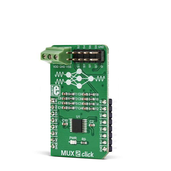
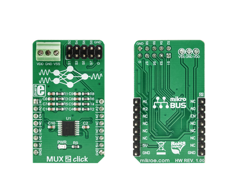
MUX 2 click is a Click board that switches one of the eight inputs to one output. It employs the MUX508, a modern CMOS analog multiplexing integrated circuit, produced by Texas Instruments.

No Abuse Reported

Do you want to subscribe in order to receive notifications regarding "MUX 2 click" changes.

Do you want to unsubscribe in order to stop receiving notifications regarding "MUX 2 click" changes.

Do you want to report abuse regarding "MUX 2 click".

  • mikroSDK Library 2.0.0.0
  • Comments (0)
DOWNLOAD LINK RELATED COMPILER CONTAINS
mikroBasic PRO for ARM
  • lib
  • src
  • exa
  • hlp
  • hex
  • sch
  • pcb
  • doc
mikroBasic PRO for AVR
  • lib
  • src
  • exa
  • hlp
  • hex
  • sch
  • pcb
  • doc
mikroBasic PRO for dsPIC30/33 & PIC24
  • lib
  • src
  • exa
  • hlp
  • hex
  • sch
  • pcb
  • doc
mikroBasic PRO for FT90x
  • lib
  • src
  • exa
  • hlp
  • hex
  • sch
  • pcb
  • doc
mikroBasic PRO for PIC
  • lib
  • src
  • exa
  • hlp
  • hex
  • sch
  • pcb
  • doc
mikroBasic PRO for PIC32
  • lib
  • src
  • exa
  • hlp
  • hex
  • sch
  • pcb
  • doc
mikroC PRO for ARM
  • lib
  • src
  • exa
  • hlp
  • hex
  • sch
  • pcb
  • doc
mikroC PRO for AVR
  • lib
  • src
  • exa
  • hlp
  • hex
  • sch
  • pcb
  • doc
mikroC PRO for dsPIC30/33 & PIC24
  • lib
  • src
  • exa
  • hlp
  • hex
  • sch
  • pcb
  • doc
mikroC PRO for FT90x
  • lib
  • src
  • exa
  • hlp
  • hex
  • sch
  • pcb
  • doc
mikroC PRO for PIC
  • lib
  • src
  • exa
  • hlp
  • hex
  • sch
  • pcb
  • doc
mikroC PRO for PIC32
  • lib
  • src
  • exa
  • hlp
  • hex
  • sch
  • pcb
  • doc
mikroPascal PRO for ARM
  • lib
  • src
  • exa
  • hlp
  • hex
  • sch
  • pcb
  • doc
mikroPascal PRO for AVR
  • lib
  • src
  • exa
  • hlp
  • hex
  • sch
  • pcb
  • doc
mikroPascal PRO for dsPIC30/33 & PIC24
  • lib
  • src
  • exa
  • hlp
  • hex
  • sch
  • pcb
  • doc
mikroPascal PRO for FT90x
  • lib
  • src
  • exa
  • hlp
  • hex
  • sch
  • pcb
  • doc
mikroPascal PRO for PIC
  • lib
  • src
  • exa
  • hlp
  • hex
  • sch
  • pcb
  • doc
mikroPascal PRO for PIC32
  • lib
  • src
  • exa
  • hlp
  • hex
  • sch
  • pcb
  • doc

mikroSDK Library Blog

MUX 2 click

MUX 2 click

Native view of the MUX 2 Click board.

View full image
MUX 2 click

MUX 2 click

Front and back view of the MUX 2 Click board.

View full image

Library Description

The library includes function for set current active mux channel and function for enable or disble mux device.

Key functions:

  • void mux2_activeMuxChannel(uint8_t ch) - Functions for set active MUX channel
  • void mux2_deviceEnable() - Functions for enable MUX device

Examples description

The application is composed of the three sections :

  • System Initialization - Sets RST pin, CS pin, PWM pin and INT pin as OUTPUT
  • Application Initialization - Initialization driver init end enable device
  • Application Task - (code snippet) - Sets the current active channel. Changes the channel every 5 sec.
void applicationTask()
{
     mux2_activeMuxChannel(_MUX2_CHANNEL_S1);
     Delay_ms( 5000 );
     mux2_activeMuxChannel(_MUX2_CHANNEL_S2);
     Delay_ms( 5000 );
     mux2_activeMuxChannel(_MUX2_CHANNEL_S3);
     Delay_ms( 5000 );
     mux2_activeMuxChannel(_MUX2_CHANNEL_S4);
     Delay_ms( 5000 );
     mux2_activeMuxChannel(_MUX2_CHANNEL_S5);
     Delay_ms( 5000 );
     mux2_activeMuxChannel(_MUX2_CHANNEL_S6);
     Delay_ms( 5000 );
     mux2_activeMuxChannel(_MUX2_CHANNEL_S7);
     Delay_ms( 5000 );
     mux2_activeMuxChannel(_MUX2_CHANNEL_S8);
     Delay_ms( 5000 );

}

Other mikroE Libraries used in the example:

  • GPIO

Additional notes and information

Depending on the development board you are using, you may need USB UART clickUSB UART 2 click or RS232 click to connect to your PC, for development systems with no UART to USB interface available on the board. The terminal available in all MikroElektronika compilers, or any other terminal application of your choice, can be used to read the message.

ALSO FROM THIS AUTHOR

AMR Current click

5

The AMR Current Click is a Click board which features the MCR1101-20-5, an AMR based integrated current sensor from ACEINNA.

[Learn More]

AWS IoT Click

0

AWS IoT Click is a compact add-on board that allows users to easily connected to AWS IoT services and securely interact with cloud applications and other devices. This board features the ESP32-C3-MINI-1-N4-A, a small 2.4GHz WiFi (802.11 b/g/n) and Bluetooth® 5 module from Espressif Systems that use ESP32C3 series of SoC RISCV single-core microprocessor (ESP32-C3FN4) with 4MB flash in a single chip package. The module uses UART communication alongside several other features like standalone possibility via USB interface, firmware boot, JTAG for debugging, and others.

[Learn More]

EEPROM 3 click

2

EEPROM 3 click carries Atmel’s AT24CM02 DIP-8 socket EEPROM chip with 256 KB of memory. The board communicates with the target MCU through the mikroBUS I2C interface (SCL, SDA pins) with speeds up to 1 MHz. The chip allows for an entire page of data to be written in a single cycle. The board is designed to use either a 3.3V or a 5V power supply.

[Learn More]