TOP Contributors

  1. MIKROE (2784 codes)
  2. Alcides Ramos (405 codes)
  3. Shawon Shahryiar (307 codes)
  4. jm_palomino (133 codes)
  5. Bugz Bensce (97 codes)
  6. S P (73 codes)
  7. dany (71 codes)
  8. MikroBUS.NET Team (35 codes)
  9. NART SCHINACKOW (34 codes)
  10. Armstrong Subero (27 codes)

Most Downloaded

  1. Timer Calculator (141957 times)
  2. FAT32 Library (75144 times)
  3. Network Ethernet Library (59420 times)
  4. USB Device Library (49409 times)
  5. Network WiFi Library (45227 times)
  6. FT800 Library (44811 times)
  7. GSM click (31367 times)
  8. mikroSDK (30365 times)
  9. microSD click (27741 times)
  10. PID Library (27595 times)
Libstock prefers package manager

Package Manager

We strongly encourage users to use Package manager for sharing their code on Libstock website, because it boosts your efficiency and leaves the end user with no room for error. [more info]

< Back
mikroSDK Library

POT 2 click

Rating:

5

Author: MIKROE

Last Updated: 2019-02-04

Package Version: 1.0.0.0

mikroSDK Library: 1.0.0.0

Category: Measurements

Downloaded: 4923 times

Not followed.

License: MIT license  

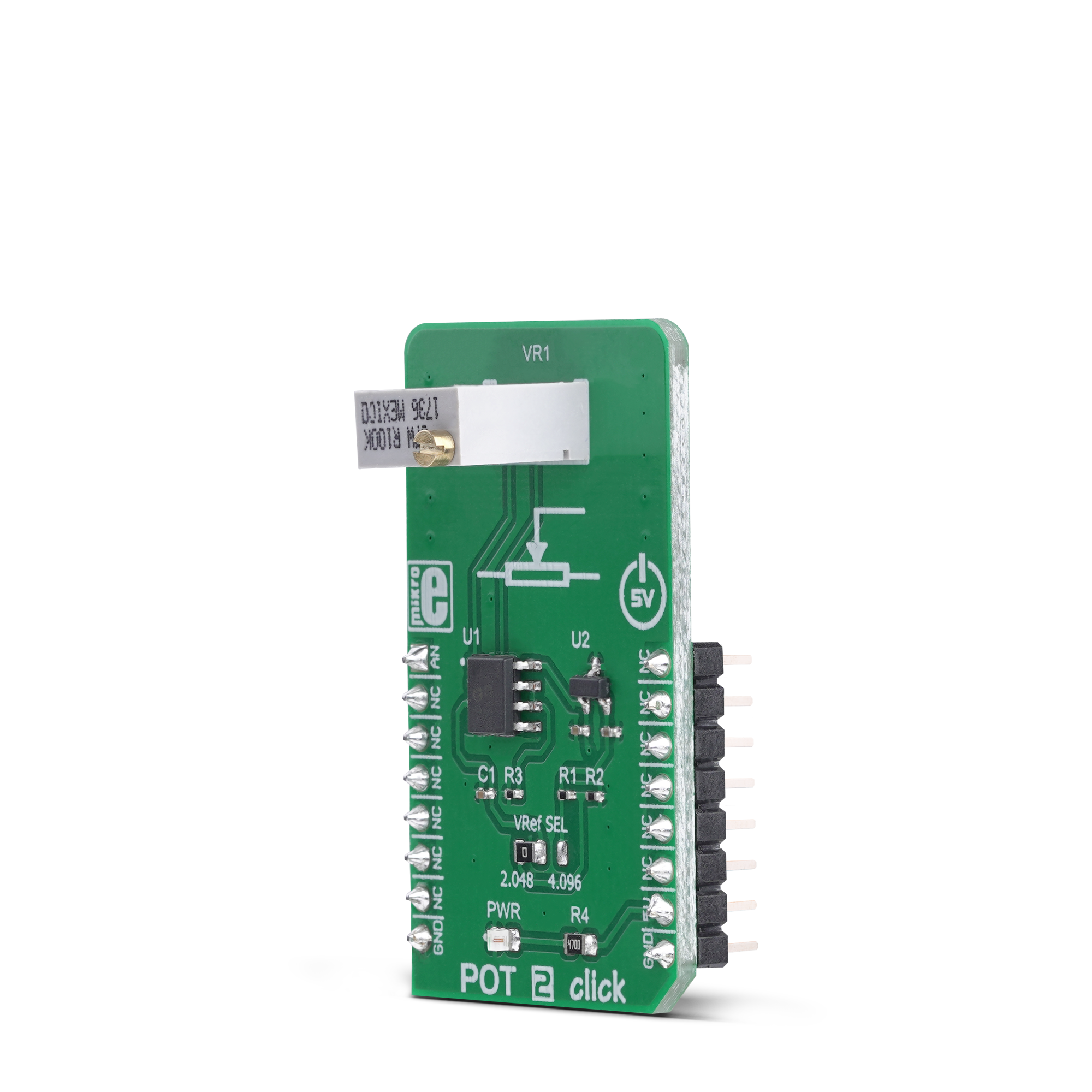
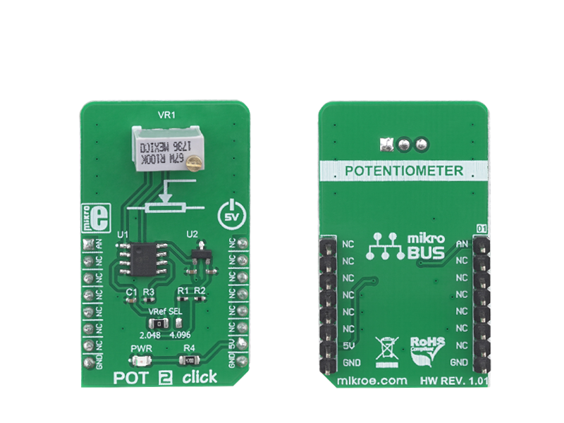
POT 2 click is a Click board with the accurate selectable reference voltage output. By utilizing a multi-turn precision potentiometer, this Click board can provide very accurate voltage output on the AN pin of the mikroBUS.

No Abuse Reported

Do you want to subscribe in order to receive notifications regarding "POT 2 click" changes.

Do you want to unsubscribe in order to stop receiving notifications regarding "POT 2 click" changes.

Do you want to report abuse regarding "POT 2 click".

  • mikroSDK Library 2.0.0.0
  • Comments (0)
DOWNLOAD LINK RELATED COMPILER CONTAINS
mikroBasic PRO for ARM
  • lib
  • src
  • exa
  • hlp
  • hex
  • sch
  • pcb
  • doc
mikroBasic PRO for AVR
  • lib
  • src
  • exa
  • hlp
  • hex
  • sch
  • pcb
  • doc
mikroBasic PRO for dsPIC30/33 & PIC24
  • lib
  • src
  • exa
  • hlp
  • hex
  • sch
  • pcb
  • doc
mikroBasic PRO for FT90x
  • lib
  • src
  • exa
  • hlp
  • hex
  • sch
  • pcb
  • doc
mikroBasic PRO for PIC
  • lib
  • src
  • exa
  • hlp
  • hex
  • sch
  • pcb
  • doc
mikroBasic PRO for PIC32
  • lib
  • src
  • exa
  • hlp
  • hex
  • sch
  • pcb
  • doc
mikroC PRO for ARM
  • lib
  • src
  • exa
  • hlp
  • hex
  • sch
  • pcb
  • doc
mikroC PRO for AVR
  • lib
  • src
  • exa
  • hlp
  • hex
  • sch
  • pcb
  • doc
mikroC PRO for dsPIC30/33 & PIC24
  • lib
  • src
  • exa
  • hlp
  • hex
  • sch
  • pcb
  • doc
mikroC PRO for FT90x
  • lib
  • src
  • exa
  • hlp
  • hex
  • sch
  • pcb
  • doc
mikroC PRO for PIC
  • lib
  • src
  • exa
  • hlp
  • hex
  • sch
  • pcb
  • doc
mikroC PRO for PIC32
  • lib
  • src
  • exa
  • hlp
  • hex
  • sch
  • pcb
  • doc
mikroPascal PRO for ARM
  • lib
  • src
  • exa
  • hlp
  • hex
  • sch
  • pcb
  • doc
mikroPascal PRO for AVR
  • lib
  • src
  • exa
  • hlp
  • hex
  • sch
  • pcb
  • doc
mikroPascal PRO for dsPIC30/33 & PIC24
  • lib
  • src
  • exa
  • hlp
  • hex
  • sch
  • pcb
  • doc
mikroPascal PRO for FT90x
  • lib
  • src
  • exa
  • hlp
  • hex
  • sch
  • pcb
  • doc
mikroPascal PRO for PIC
  • lib
  • src
  • exa
  • hlp
  • hex
  • sch
  • pcb
  • doc
mikroPascal PRO for PIC32
  • lib
  • src
  • exa
  • hlp
  • hex
  • sch
  • pcb
  • doc

mikroSDK Library Blog

POT 2 click

POT 2 click

Native view of the POT 2 click board.

View full image
POT 2 click

POT 2 click

Front and back view of the POT 2 click board.

View full image

Library Description

The library contains the functions needed to start and read the ADC values.

Key functions:

  • void pot2_adcInit() - ADC Init function.
  • void pot2_adcSetInputChannel() - ADC set input channel function.
  • uint32_t pot2_adcRead() - ADC read function.

Examples description

The application is composed of the three sections :

  • System Initialization - Initializes LOG to print data that is read from ADC.
  • Application Initialization - Initialization ADC Init and sets ADC input channel.
  • Application Task - (code snippet) - Reads data from ADC and logs data to USBUART every 500 ms.
void applicationTask()
{
    uint16_t ADC_value;
    char demoText[ 50 ];
        
    ADC_value = pot2_adcRead();
    
    WordToHex(ADC_value, demoText);
    mikrobus_logWrite(" ADC value: 0x", _LOG_TEXT);
    mikrobus_logWrite(demoText, _LOG_LINE);
    Delay_ms( 500 );
}

Other mikroE Libraries used in the example:

  • ADC

Additional notes and informations

Depending on the development board you are using, you may need USB UART clickUSB UART 2 clickor RS232 click to connect to your PC, for development systems with no UART to USB interface available on the board. The terminal available in all MikroElektronika compilers, or any other terminal application of your choice, can be used to read the message.

ALSO FROM THIS AUTHOR

Signal Relay click

0

Signal Relay click can be used for ON/OFF control in various devices. It carries four ultra-small GV5-1 PCB relays from Omron and runs on a 5V power supply. Signal Relay click communicates with the target MCU over the following mikroBUS pins: AN, RST, CS and PWM.

[Learn More]

Load Cell 5 Click

0

Load Cell 5 Click is a compact add-on board that represents a weigh scale solution. This board features the AD7780, a pin-programmable, low power, 24-bit sigma-delta ΣΔ ADC from Analog Devices. It interfaces directly to the load cell, where the low-level signal from the load cell is amplified by the AD7780’s internal low noise programmable gain amplifier programmed to operate with a gain of 128 or 1. It also has a power-down mode allowing the user to switch off the power to the bridge sensor and power-down the AD7780 when not converting, increasing the product battery life. This Click board™ has many features that make it a perfect solution for safety-critical and weight measurement applications.

[Learn More]

Proximity 2 Click

0

Proximity 2 Click features MAX44000, an IC that integrates an ambient light as well as a proximity sensor. The chip consists of an array of photodiodes that convert light into current, which the internal circuitry then converts into a digital value.

[Learn More]