TOP Contributors

  1. MIKROE (2661 codes)
  2. Alcides Ramos (357 codes)
  3. Shawon Shahryiar (307 codes)
  4. jm_palomino (112 codes)
  5. Chisanga Mumba (90 codes)
  6. S P (73 codes)
  7. dany (71 codes)
  8. MikroBUS.NET Team (35 codes)
  9. NART SCHINACKOW (34 codes)
  10. Armstrong Subero (27 codes)

Most Downloaded

  1. Timer Calculator (137023 times)
  2. FAT32 Library (70144 times)
  3. Network Ethernet Library (56030 times)
  4. USB Device Library (46353 times)
  5. Network WiFi Library (41968 times)
  6. FT800 Library (41296 times)
  7. GSM click (29063 times)
  8. mikroSDK (26502 times)
  9. PID Library (26452 times)
  10. microSD click (25424 times)
Libstock prefers package manager

Package Manager

We strongly encourage users to use Package manager for sharing their code on Libstock website, because it boosts your efficiency and leaves the end user with no room for error. [more info]

< Back
mikroSDK Library

STSPIN250 click

Rating:

5

Author: MIKROE

Last Updated: 2019-05-07

Package Version: 1.0.0.0

mikroSDK Library: 1.0.0.0

Category: Brushed

Downloaded: 3377 times

Not followed.

License: MIT license  

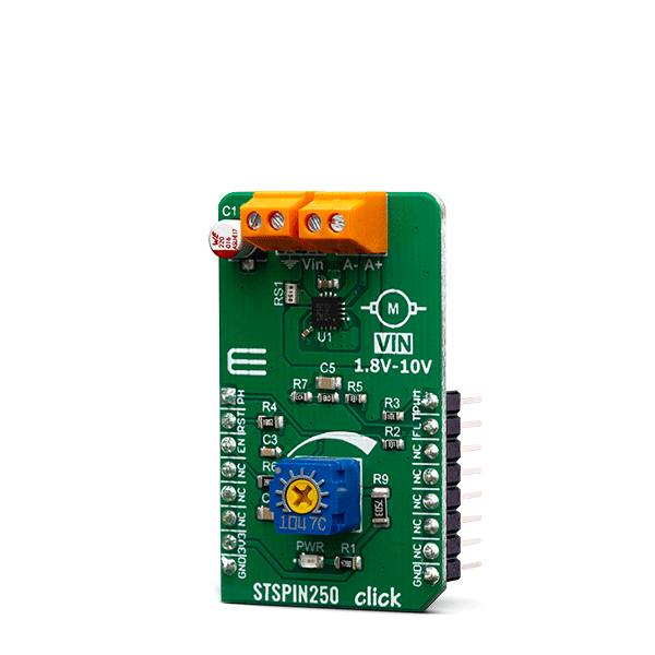
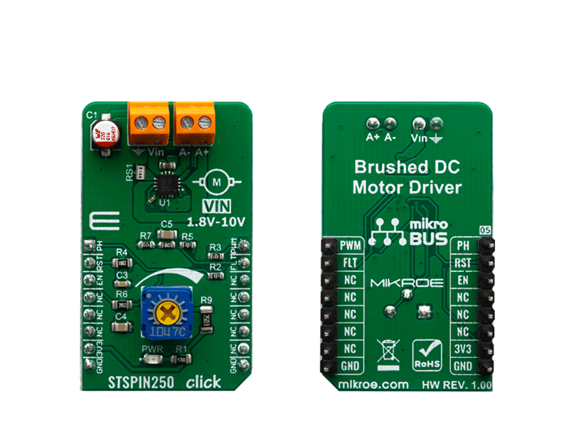
STSPIN250 click is a brushed DC motor driver with the current limiting and current sensing. It is based on the STSPIN250, a low voltage DC brushed motor driver.

No Abuse Reported

Do you want to subscribe in order to receive notifications regarding "STSPIN250 click" changes.

Do you want to unsubscribe in order to stop receiving notifications regarding "STSPIN250 click" changes.

Do you want to report abuse regarding "STSPIN250 click".

  • mikroSDK Library 2.0.0.0
  • Comments (0)
DOWNLOAD LINK RELATED COMPILER CONTAINS
mikroBasic PRO for ARM
  • lib
  • src
  • exa
  • hlp
  • hex
  • sch
  • pcb
  • doc
mikroBasic PRO for AVR
  • lib
  • src
  • exa
  • hlp
  • hex
  • sch
  • pcb
  • doc
mikroBasic PRO for dsPIC30/33 & PIC24
  • lib
  • src
  • exa
  • hlp
  • hex
  • sch
  • pcb
  • doc
mikroBasic PRO for FT90x
  • lib
  • src
  • exa
  • hlp
  • hex
  • sch
  • pcb
  • doc
mikroBasic PRO for PIC
  • lib
  • src
  • exa
  • hlp
  • hex
  • sch
  • pcb
  • doc
mikroBasic PRO for PIC32
  • lib
  • src
  • exa
  • hlp
  • hex
  • sch
  • pcb
  • doc
mikroC PRO for ARM
  • lib
  • src
  • exa
  • hlp
  • hex
  • sch
  • pcb
  • doc
mikroC PRO for AVR
  • lib
  • src
  • exa
  • hlp
  • hex
  • sch
  • pcb
  • doc
mikroC PRO for dsPIC30/33 & PIC24
  • lib
  • src
  • exa
  • hlp
  • hex
  • sch
  • pcb
  • doc
mikroC PRO for FT90x
  • lib
  • src
  • exa
  • hlp
  • hex
  • sch
  • pcb
  • doc
mikroC PRO for PIC
  • lib
  • src
  • exa
  • hlp
  • hex
  • sch
  • pcb
  • doc
mikroC PRO for PIC32
  • lib
  • src
  • exa
  • hlp
  • hex
  • sch
  • pcb
  • doc
mikroPascal PRO for ARM
  • lib
  • src
  • exa
  • hlp
  • hex
  • sch
  • pcb
  • doc
mikroPascal PRO for AVR
  • lib
  • src
  • exa
  • hlp
  • hex
  • sch
  • pcb
  • doc
mikroPascal PRO for dsPIC30/33 & PIC24
  • lib
  • src
  • exa
  • hlp
  • hex
  • sch
  • pcb
  • doc
mikroPascal PRO for FT90x
  • lib
  • src
  • exa
  • hlp
  • hex
  • sch
  • pcb
  • doc
mikroPascal PRO for PIC
  • lib
  • src
  • exa
  • hlp
  • hex
  • sch
  • pcb
  • doc
mikroPascal PRO for PIC32
  • lib
  • src
  • exa
  • hlp
  • hex
  • sch
  • pcb
  • doc

mikroSDK Library Blog

STSPIN250

STSPIN250

Native view of the STSPIN250 board.

View full image
STSPIN250

STSPIN250

Front and back view of the STSPIN250 board.

View full image

Library Description

Initializes and defines gpio driver and constant values witch can be used in example code, and also performs the chip enable.

Key functions:

  • void stspin250_enable(uint8_t state) - Function for enable or disable device.
  • void stspin250_setPH(uint8_t state) - Function for select the direction of rotation of the motor.

Examples description

The application is composed of the three sections :

  • System Initialization - Sets AN,RST,CS and PWM pin as OUTPUT and INT pin as INPUT.
  • Application Initialization - Initialization driver init, PWM init and enable device.
  • Application Task - (code snippet) - Changes the PWM dutyCycle and controls the motor speed. You can change the direction of the motor rotation by setting PH to 0 or 1..
void applicationTask()
{
// PWM DEMO EXAMPLE
    _dutyCycle += 250;
    stspin250_pwmSetDuty(_dutyCycle);
    if (_dutyCycle > 40000 )
    {
        _dutyCycle = 0;
        stspin250_pwmStop();
        Delay_ms(2000);
        stspin250_pwmStart();
    }
	stspin250_setPH(1);
    Delay_ms( 200 );
}

Other mikroE Libraries used in the example:

  • GPIO
  • PWM

Additional notes and informations

Depending on the development board you are using, you may need USB UART clickUSB UART 2 click or RS232 click to connect to your PC, for development systems with no UART to USB interface available on the board. The terminal available in all MikroElektronika compilers, or any other terminal application of your choice, can be used to read the message.

ALSO FROM THIS AUTHOR

Color 9 click

0

Color 9 Click is a very accurate color sensing Click board which features the APDS-9250, IR and ambient light sensor, from Broadcom. It contains a specially designed matrix of photosensitive elements, which can sense red, green, blue and IR component.

[Learn More]

Color 17 click

0

Color 17 Click is a compact add-on board representing an accurate color-sensing solution. This board features the OPT4048, a high-speed precision tristimulus XYZ color sensor from Texas Instruments. The sensor has four sensing channels and uses precision optical filters to mimic the normal vision of the human eye. The OPT4048 also has 12 configurable conversion times that range from 600μs up to 800ms, with measurements that can be read synchronously or asynchronously. It is not excessively sensitive to micro-shadows and the small particles on the optical surface.

[Learn More]

Buck 19 click

0

Buck 19 Click is a compact add-on board that steps down the voltage from its input (supply) to its output (load). This board features the STPD01, a programmable synchronous buck converter from STMicroelectronics, providing power supply in applications following USB power delivery specifications. The STPD01 provides the desired voltage levels required by USB power delivery systems (USB PD 3.0) via I2C serial interface up to 60W output power, more precisely voltages in the range of 3V to 20V with a step of 20mV minimum, and currents from 0.1A to 3A with a minimum in steps of 50mA. It also offers advanced protection features such as overvoltage, overcurrent, and overtemperature detections.

[Learn More]