TOP Contributors

  1. MIKROE (2784 codes)
  2. Alcides Ramos (405 codes)
  3. Shawon Shahryiar (307 codes)
  4. jm_palomino (133 codes)
  5. Bugz Bensce (97 codes)
  6. S P (73 codes)
  7. dany (71 codes)
  8. MikroBUS.NET Team (35 codes)
  9. NART SCHINACKOW (34 codes)
  10. Armstrong Subero (27 codes)

Most Downloaded

  1. Timer Calculator (141892 times)
  2. FAT32 Library (75039 times)
  3. Network Ethernet Library (59344 times)
  4. USB Device Library (49347 times)
  5. Network WiFi Library (45156 times)
  6. FT800 Library (44701 times)
  7. GSM click (31300 times)
  8. mikroSDK (30264 times)
  9. microSD click (27685 times)
  10. PID Library (27576 times)
Libstock prefers package manager

Package Manager

We strongly encourage users to use Package manager for sharing their code on Libstock website, because it boosts your efficiency and leaves the end user with no room for error. [more info]

< Back
mikroSDK Library

Buck-Boost 3 click

Rating:

6

Author: MIKROE

Last Updated: 2019-01-09

Package Version: 1.0.0.0

mikroSDK Library: 1.0.0.0

Category: Buck-Boost

Downloaded: 4648 times

Not followed.

License: MIT license  

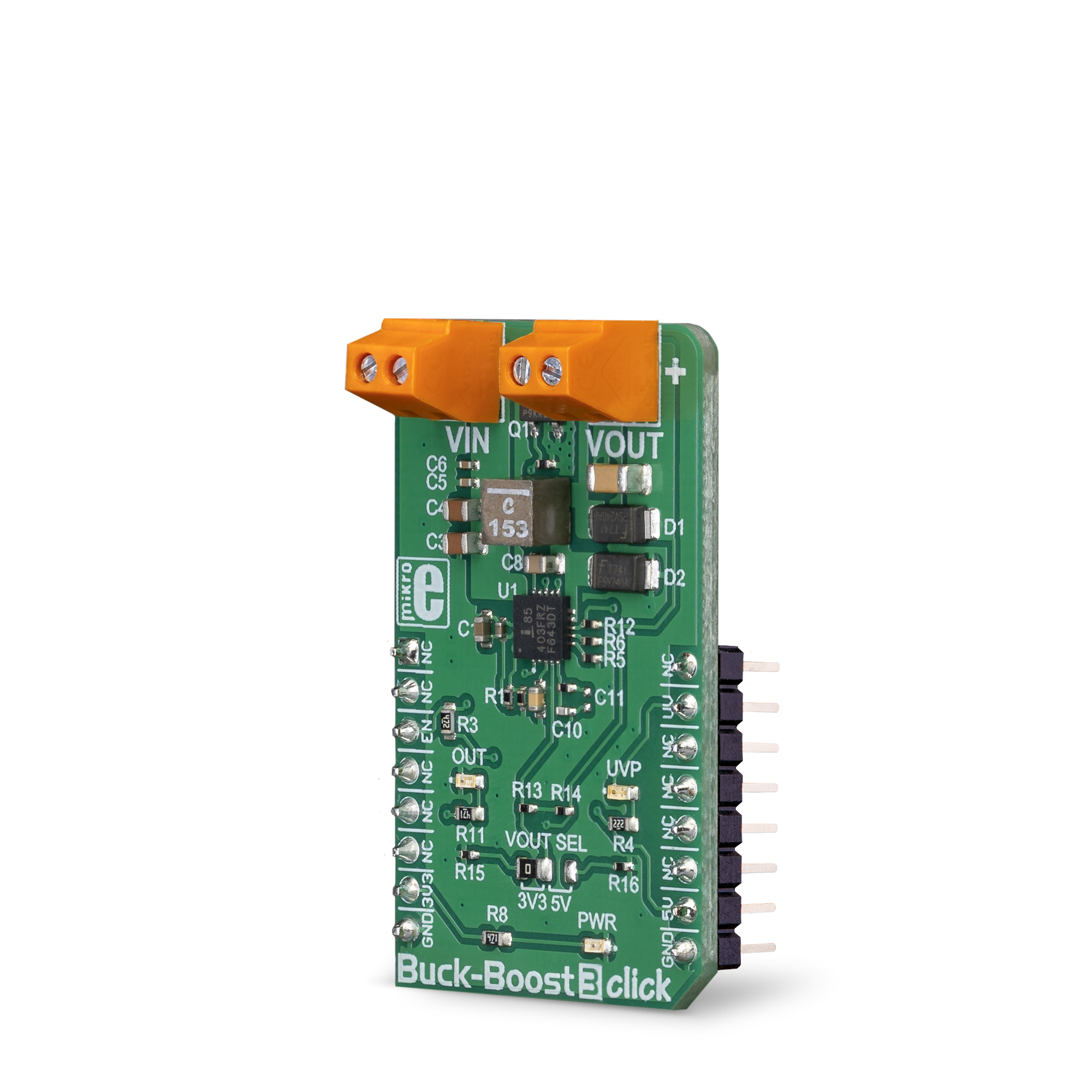
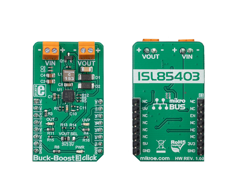
The Buck-Boost 3 click is a voltage converter/regulator, which is able to provide a regulated voltage of 3.3V or 5V on the output, even when the input voltage drops under 3V.

No Abuse Reported

Do you want to subscribe in order to receive notifications regarding "Buck-Boost 3 click" changes.

Do you want to unsubscribe in order to stop receiving notifications regarding "Buck-Boost 3 click" changes.

Do you want to report abuse regarding "Buck-Boost 3 click".

  • mikroSDK Library 2.0.0.0
  • Comments (0)
DOWNLOAD LINK RELATED COMPILER CONTAINS
mikroBasic PRO for ARM
  • lib
  • src
  • exa
  • hlp
  • hex
  • sch
  • pcb
  • doc
mikroBasic PRO for AVR
  • lib
  • src
  • exa
  • hlp
  • hex
  • sch
  • pcb
  • doc
mikroBasic PRO for dsPIC30/33 & PIC24
  • lib
  • src
  • exa
  • hlp
  • hex
  • sch
  • pcb
  • doc
mikroBasic PRO for FT90x
  • lib
  • src
  • exa
  • hlp
  • hex
  • sch
  • pcb
  • doc
mikroBasic PRO for PIC
  • lib
  • src
  • exa
  • hlp
  • hex
  • sch
  • pcb
  • doc
mikroBasic PRO for PIC32
  • lib
  • src
  • exa
  • hlp
  • hex
  • sch
  • pcb
  • doc
mikroC PRO for ARM
  • lib
  • src
  • exa
  • hlp
  • hex
  • sch
  • pcb
  • doc
mikroC PRO for AVR
  • lib
  • src
  • exa
  • hlp
  • hex
  • sch
  • pcb
  • doc
mikroC PRO for dsPIC30/33 & PIC24
  • lib
  • src
  • exa
  • hlp
  • hex
  • sch
  • pcb
  • doc
mikroC PRO for FT90x
  • lib
  • src
  • exa
  • hlp
  • hex
  • sch
  • pcb
  • doc
mikroC PRO for PIC
  • lib
  • src
  • exa
  • hlp
  • hex
  • sch
  • pcb
  • doc
mikroC PRO for PIC32
  • lib
  • src
  • exa
  • hlp
  • hex
  • sch
  • pcb
  • doc
mikroPascal PRO for ARM
  • lib
  • src
  • exa
  • hlp
  • hex
  • sch
  • pcb
  • doc
mikroPascal PRO for AVR
  • lib
  • src
  • exa
  • hlp
  • hex
  • sch
  • pcb
  • doc
mikroPascal PRO for dsPIC30/33 & PIC24
  • lib
  • src
  • exa
  • hlp
  • hex
  • sch
  • pcb
  • doc
mikroPascal PRO for FT90x
  • lib
  • src
  • exa
  • hlp
  • hex
  • sch
  • pcb
  • doc
mikroPascal PRO for PIC
  • lib
  • src
  • exa
  • hlp
  • hex
  • sch
  • pcb
  • doc
mikroPascal PRO for PIC32
  • lib
  • src
  • exa
  • hlp
  • hex
  • sch
  • pcb
  • doc

mikroSDK Library Blog

Buck-Boost 3 click

Buck-Boost 3 click

Native view of the Buck-Boost 3 click board.

View full image
Buck-Boost 3 click

Buck-Boost 3 click

Front and back view of the Buck-Boost 3 click board.

View full image

Library Description

The library includes features to enable or disable devices and functions to check if the input voltage is below the operating voltage.

Key functions:

  • void buckboost3_enable(uint8_t state) - Function for enable/disable device
  • uint8_t buckboost3_getInterruptState() - Function for get Intterupt pin state

Examples description

The application is composed of the three sections :

  • System Initialization - Sets INT pin as INPUT and CS pin as OUTPUT
  • Application Initialization - Initialization driver init and enable device
  • Application Task - (code snippet) - It checks if the input voltage is below the operating voltage.
void applicationTask()
{
    uint8_t PGOOD_state;
    
    PGOOD_state = buckboost3_getInterruptState();
    if (PGOOD_state == 0)
    {
        mikrobus_logWrite(" Low input voltage !!!", _LOG_LINE);
    }
    Delay_ms( 1000 );
}

Other mikroE Libraries used in the example:

  • GPIO

Additional notes and information

Depending on the development board you are using, you may need USB UART clickUSB UART 2 click or RS232 click to connect to your PC, for development systems with no UART to USB interface available on the board. The terminal available in all MikroElektronika compilers, or any other terminal application of your choice, can be used to read the message.

ALSO FROM THIS AUTHOR

RTC Click

0

RTC Click is an accessory board in mikroBus™ form factor. It features the PCF8583 serial real-time clock (RTC)

[Learn More]

BarGraph 2 click

5

BarGraph 2 click is a 10-segment bar graph display click, which uses a high-quality, multicolor bar graph LED display. The bar graph display is a very popular device for displaying various properties, whether it be an audio level, current/voltage level, position of the encoder, or something else.

[Learn More]

Smart Sens 2 Click

0

Smart Sens 2 Click is a compact add-on board that contains a smart sensor system with an integrated IMU sensor. This board utilizes the BHI260AP, BME688, BMP390, and BMM150, an ultra-low-power programmable smart sensor, environmental and pressure sensor, and a magnetometer from Bosch Sensortec. The BHI260AP includes a powerful 32-bit MCU and a 6-axis IMU (3-axis accelerometer and 3-axis gyroscope) alongside an event-driven software framework. In addition to its internal functions also perform signal data processing from several onboard sensors performing measurements of various parameters such as an environmental and magnetic field. In addition to these primary functions, this Click board™ allows users to select the desired serial interface, use the debug interface, and select BOOT mode.

[Learn More]