TOP Contributors

  1. MIKROE (2652 codes)
  2. Alcides Ramos (351 codes)
  3. Shawon Shahryiar (307 codes)
  4. jm_palomino (112 codes)
  5. Chisanga Mumba (90 codes)
  6. S P (73 codes)
  7. dany (71 codes)
  8. MikroBUS.NET Team (35 codes)
  9. NART SCHINACKOW (34 codes)
  10. Armstrong Subero (27 codes)

Most Downloaded

  1. Timer Calculator (136628 times)
  2. FAT32 Library (69833 times)
  3. Network Ethernet Library (55887 times)
  4. USB Device Library (46225 times)
  5. Network WiFi Library (41861 times)
  6. FT800 Library (41080 times)
  7. GSM click (28942 times)
  8. PID Library (26402 times)
  9. mikroSDK (26316 times)
  10. microSD click (25328 times)
Libstock prefers package manager

Package Manager

We strongly encourage users to use Package manager for sharing their code on Libstock website, because it boosts your efficiency and leaves the end user with no room for error. [more info]

< Back
mikroSDK Library

RTC 8 click

Rating:

5

Author: MIKROE

Last Updated: 2019-05-23

Package Version: 1.0.0.0

mikroSDK Library: 1.0.0.0

Category: RTC

Downloaded: 3198 times

Not followed.

License: MIT license  

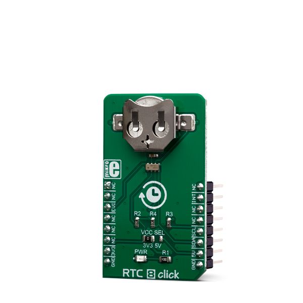
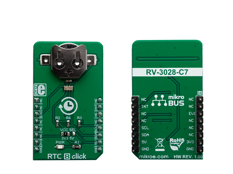
RTC 8 click is a real time clock module which has an extremely low power consumption, allowing it to be used with a single button cell battery, for an extended period of time.

No Abuse Reported

Do you want to subscribe in order to receive notifications regarding "RTC 8 click" changes.

Do you want to unsubscribe in order to stop receiving notifications regarding "RTC 8 click" changes.

Do you want to report abuse regarding "RTC 8 click".

  • mikroSDK Library 2.0.0.0
  • Comments (0)
DOWNLOAD LINK RELATED COMPILER CONTAINS
mikroBasic PRO for ARM
  • lib
  • src
  • exa
  • hlp
  • hex
  • sch
  • pcb
  • doc
mikroBasic PRO for AVR
  • lib
  • src
  • exa
  • hlp
  • hex
  • sch
  • pcb
  • doc
mikroBasic PRO for dsPIC30/33 & PIC24
  • lib
  • src
  • exa
  • hlp
  • hex
  • sch
  • pcb
  • doc
mikroBasic PRO for FT90x
  • lib
  • src
  • exa
  • hlp
  • hex
  • sch
  • pcb
  • doc
mikroBasic PRO for PIC
  • lib
  • src
  • exa
  • hlp
  • hex
  • sch
  • pcb
  • doc
mikroBasic PRO for PIC32
  • lib
  • src
  • exa
  • hlp
  • hex
  • sch
  • pcb
  • doc
mikroC PRO for ARM
  • lib
  • src
  • exa
  • hlp
  • hex
  • sch
  • pcb
  • doc
mikroC PRO for AVR
  • lib
  • src
  • exa
  • hlp
  • hex
  • sch
  • pcb
  • doc
mikroC PRO for dsPIC30/33 & PIC24
  • lib
  • src
  • exa
  • hlp
  • hex
  • sch
  • pcb
  • doc
mikroC PRO for FT90x
  • lib
  • src
  • exa
  • hlp
  • hex
  • sch
  • pcb
  • doc
mikroC PRO for PIC
  • lib
  • src
  • exa
  • hlp
  • hex
  • sch
  • pcb
  • doc
mikroC PRO for PIC32
  • lib
  • src
  • exa
  • hlp
  • hex
  • sch
  • pcb
  • doc
mikroPascal PRO for ARM
  • lib
  • src
  • exa
  • hlp
  • hex
  • sch
  • pcb
  • doc
mikroPascal PRO for AVR
  • lib
  • src
  • exa
  • hlp
  • hex
  • sch
  • pcb
  • doc
mikroPascal PRO for dsPIC30/33 & PIC24
  • lib
  • src
  • exa
  • hlp
  • hex
  • sch
  • pcb
  • doc
mikroPascal PRO for FT90x
  • lib
  • src
  • exa
  • hlp
  • hex
  • sch
  • pcb
  • doc
mikroPascal PRO for PIC
  • lib
  • src
  • exa
  • hlp
  • hex
  • sch
  • pcb
  • doc
mikroPascal PRO for PIC32
  • lib
  • src
  • exa
  • hlp
  • hex
  • sch
  • pcb
  • doc

mikroSDK Library Blog

RTC 8 click

RTC 8 click

Native view of the RTC 8 click board.

View full image
RTC 8 click

RTC 8 click

Front and back view of the RTC 8 click board.

View full image

Library Description

The library initializes and defines the I2C drivers and drivers that offer a choice of writing data in register and reading data from the register in BCD and DEC format. The library includes function for sets Time, Date, new Alarm and set/get UNIX time. The user can set and read Time and Date data, especially using the functions for reading and writing data. The library includes functions for setting the desired alarm, disabling alarm and checking whether an alarm has been activated.

Key functions:

  • uint8_t rtc8_readData(uint8_t reg) - Read one byte data from register in DEC format.
  • uint32_t rtc8_getUNIX() - Get current UNIX time.
  • uint8_t rtc8_setTime(uint8_t _hours, uint8_t _minutes, uint8_t _seconds) - Set new start time - 24 hour format.
  • uint8_t rtc8_setDate(uint8_t _date, uint8_t _month, uint8_t _year) - Set new start date.

Examples description

The application is composed of the three sections :

  • System Initialization - Initializes I2C module and sets INT pin as INPUT and CS pin as OUTPUT.
  • Application Initialization - Initialization driver init, settings RTC for work and sets start time/date and new alarm.
  • Application Task - Read current Time, Date and UNIX time and checks if the alarm is active.

Note: Comment the lines for setting date and time if you would like the module to keep counting time after a reset or shut down.

	void applicationTask()
{
    uint8_t seconds;
    uint8_t minutes;
    uint8_t hours;
    uint8_t _weekday;
    uint8_t date;
    uint8_t month;
    uint8_t year;
    uint8_t status;
    uint32_t UNIX_time;
    char demoText[50];
    
    // Time
    seconds = rtc8_readData(_RTC8_REG_SECONDS);
    minutes = rtc8_readData(_RTC8_REG_MINUTES);
    hours = rtc8_readData(_RTC8_REG_HOURS);
    // Date
    _weekday = rtc8_readData(_RTC8_REG_WEEKDAY);
    date = rtc8_readData(_RTC8_REG_DATE);
    month = rtc8_readData(_RTC8_REG_MONTH);
    year = rtc8_readData(_RTC8_REG_YEAR);
    status = rtc8_readByte(_RTC8_REG_STATUS);
    // Unix time
    UNIX_time = rtc8_getUNIX();
    
     
    mikrobus_logWrite( "Time:  ", _LOG_TEXT );
    // Houes
    IntToStr(hours, demoText);
    Ltrim(demoText);
    mikrobus_logWrite( demoText, _LOG_TEXT );
    // Minute
    mikrobus_logWrite(":", _LOG_TEXT);
    IntToStr(minutes, demoText);
    Ltrim(demoText);
    mikrobus_logWrite(demoText, _LOG_TEXT);
    // Seconds
    mikrobus_logWrite(":", _LOG_TEXT);
    IntToStr(seconds, demoText);
    Ltrim(demoText);
    mikrobus_logWrite(demoText, _LOG_LINE);

    mikrobus_logWrite( "Weekday: ", _LOG_TEXT );
    IntToStr(_weekday, demoText);
    Ltrim(demoText);
    mikrobus_logWrite( demoText, _LOG_LINE );
  
    mikrobus_logWrite( "Date:  ", _LOG_TEXT );
    // Date
    IntToStr(date, demoText);
    Ltrim(demoText);
    mikrobus_logWrite( demoText, _LOG_TEXT );
    // Month
    mikrobus_logWrite(".", _LOG_TEXT);
    IntToStr(month, demoText);
    Ltrim(demoText);
    mikrobus_logWrite(demoText, _LOG_TEXT);
    // Year
    mikrobus_logWrite(".", _LOG_TEXT);
    IntToStr(year, demoText);
    Ltrim(demoText);
    mikrobus_logWrite(demoText, _LOG_LINE);

    mikrobus_logWrite( "UNIX:  ", _LOG_TEXT );
    LongWordToStr(UNIX_time, demoText);
    Ltrim(demoText);
    mikrobus_logWrite( demoText, _LOG_LINE );

    if((status & 0x04)/4 != 0)
    {
        mikrobus_logWrite( " - Alarm Active!!!", _LOG_LINE );
        Delay_1sec();
        rtc8_writeByte(_RTC8_REG_STATUS, _RTC8_STATUS_REG_CLEAR); // Reset Alarm Flag
    }
    else
    {
        mikrobus_logWrite( " - No Alarm.", _LOG_LINE );
    }
 
    mikrobus_logWrite( "----------------------------------", _LOG_LINE );
    Delay_ms(1000);
}

Other mikroE Libraries used in the example:

  • I2C
  • UART
  • Conversions

Additional notes and informations

Depending on the development board you are using, you may need USB UART clickUSB UART 2 click or RS232 click to connect to your PC, for development systems with no UART to USB interface available on the board. The terminal available in all MikroElektronika compilers, or any other terminal application of your choice, can be used to read the message.

ALSO FROM THIS AUTHOR

Step Down 3 click

0

Step Down 3 Click is a compact add-on board that steps down the voltage from its input to its output. This board features the ST1PS03, a nano-quiescent miniaturized synchronous step-down converter with a load switch from STMicroelectronics. The ST1PS03 can provide up to 400mA output current with an input voltage ranging from 1.8V to 5.5V, specifically designed for applications where high efficiency is crucial. It also embeds a controlled switch accessible from auxiliary channel input to supply a subsystem, output voltage from 1.6V to 3.3V set using three digital control inputs, and a Power Good signal to indicate stabilized output voltages.

[Learn More]

RMS to DC click

7

RMS to DC click is a Click board that is used to convert the RMS of the input signal into a DC voltage, with a value directly readable over the I2C interface. The Click board is equipped with the LTC1968, an RMS-to-DC converter IC, which outputs an analog voltage depending on the RMS value of the input signal.

[Learn More]

Nano GPS 2 click

5

Nano GPS 2 Click features the smallest GPS module with an integrated patch antenna, the ORG1510-MK05 a module from OriginGPS. It’s the world’s smallest multi-constellation antenna module enabling high-performance in a variety of applications.

[Learn More]